| Submission Procedure |
Quality of Service Routing in a MANET with OLSRDang-Quan Nguyen Pascale Minet Abstract: Ad hoc wireless networks have enormous commercial and military potential becauseof their self-organizing capacity and mobility support. However, some specificities of these networks such as radio interferences and limited resources make more complex the quality of service(QoS) support. Indeed, on the one hand, the bandwidth offered to users is strongly affected by radio interferences. On the other hand, flooding information in such a network must be optimizedin order to save resources. Therefore, we propose in this paper, a solution taking into account radio interferences in mobile ad hoc network routing and optimizing flooding. This solution isbased on a modified version of the OLSR routing protocol that considers bandwidth requests and radio interferences in the route selection process while providing a very efficient flooding.A comparative performance evaluation based on NS simulations shows that despite the overhead due to QoS management, this solution outperforms classical OLSR in terms of QoS perceivedby the users (e.g. bandwidth amount granted to a flow and delivery rate). The efficiency of the optimized flooding is equal to that provided by the native version of OLSR. Key Words: Interference, quality of service, optimized flooding, QoS routing, OLSR, multi-point relay (MPR), local available bandwidth, admission control, ad hoc network. 1 IntroductionMobile ad hoc networks (MANETs) are made up of mobile devices that use wireless transmission for communication. They can be set up anywhere and at any time because they require neither infrastructure nor central administration. As in a wired network, application flows in a MANET have different characteristics (e.g. type and volume of information exchanged, lifetime of the interaction, packet interarrival time, with or without burst) and also different Quality of Service (QoS) requirements (e.g. delay, throughput, high priority processing). Hence, a uniform packet processing is not adequate and a QoS support taking into account various QoS requirements is needed. In a MANET, QoS management is harder than in a wired network for the following reasons:
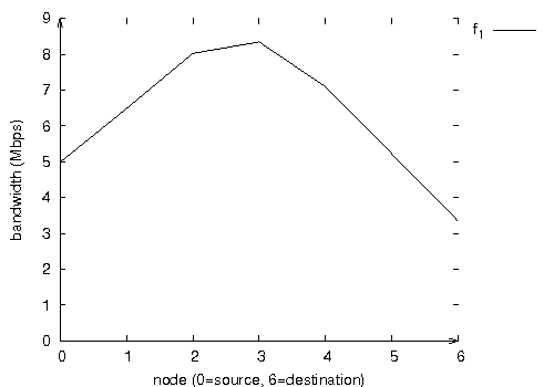
Definition 1. The transmission of a node is said to interfere with the transmission of other nodes if at the receivers, the carrier to interference ratio is lower than a threshold value. Page 56 Most QoS routing protocols consider the bandwidth as a quality of service parameter. To select a route providing the requested bandwidth, they need to know the bandwidth available at each node. Definition 2. The bandwidth available at a node, denoted LAB, is equal to the percentage of time the medium is neither busy nor in back-off state, times the medium capacity. More precisely, assuming that the MAC layer uses the IEEE 802.11b protocol, the LAB of a node is then equal to (C802.11b - bandwidth_consumed), where C802.11b is the capacity of the 802.11b wireless channel. The bandwidth consumed at a node takes into account all transmissions in the neighborhood and interference zone of that node, including all the delays resulting from those transmissions, for example, NAV settings, DIFS delays before resuming the back-off counter. Indeed, such transmissions make the channel busy and prevent this node from receiving and sending other packets. We will show the impact of the interference on the bandwidth consumed by a flow. Figure 1 illustrates the bandwidth consumed at the MAC level by a CBR flow of 1Mbps generated by node 0 and visiting successively nodes 1 to 5 to finally reach its destination node 6. We can notice that the bandwidth consumed by a flow depends on the node considered. For instance, in Figure 1, the bandwidth consumed at the source node, node 0, is 5 Mbps, whereas it is 8Mbps on node 3 and 3.5Mbps on the destination node, node 6. The results illustrated in Figures 1 and 2 have been obtained by simulation under NS-2. The packet size is 1500 bytes. The MAC layer uses the 802.11b protocol without RTS/CTS. The transmission range is set to 250m and the carrier sense range is 550m. Figure 1: Bandwidth consumed at the MAC level by a CBR flow at 1Mbps. Page 57
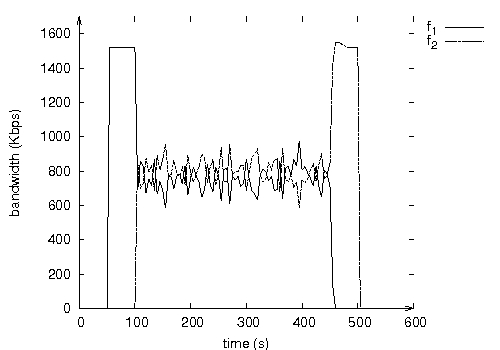
Figure 2: Useful bandwidth measured at the destination of each flow.
Therefore, the interference problem must be taken into account by QoS routing protocols and admission control: in other words, QoS routing and admission control must be interference-aware in a limited-resource environment. Page 58 For all these reasons, the goal is not to provide hard QoS guarantees, butrather to optimize the network resource utilization while satisfying application requirements. Consequently, applications must adapt to time-varying low-capacity resources provided by the network. As MANETs are not generally one-hop, routing is needed. The OLSR routing protocol, [Adjih et al. 2003], is an optimization of a pure link state algorithm. It maintains one route per destination: this route is the shortest one in terms of hop. Unfortunately, OLSR does not take into account the amount of bandwidth requested by a flow. In this paper, we propose an interference-aware QoS routing protocol based on OLSR. The performance evaluation done shows that this solution maximizes the bandwidth granted to a flow, maximizes the number of acceptable flows and increases route stability. Furthermore, in a mobile ad hoc network, disseminating information (e.g. service announcement, gateway advertisement, network topology in a proactive routing protocol) or information request (e.g. route request in a reactive routing protocol) is frequently needed. In order to avoid resources wastage, optimized flooding is required. A solution based on multipoint relays (MPR) is more adaptive than one based on a predefined connected dominating set and leads to less retransmissions. The selection of these MPRs is an important performance factor, as will be illustrated by NS2 simulation results. As a consequence, a solution based on OLSR routing providing QoS support and optimized flooding is needed. This is the purpose of this paper. The rest of this paper is organized as follows. Section 2 is a brief state of the art. It presents the native OLSR routing protocol. Variants for MPR selection are discussed with the performances of the associated MPR flooding. The interference effect on routing complexity is pointed out. Different solutions supporting QoS are described. In Section 3, we propose our solution enhancing OLSR with an interference-aware QoS support while keeping the excellent performances of MPR flooding. This solution is based on the following building blocks: QoS routing based on OLSR, QoS signaling based on local available bandwith and admission control aware of interferences. In Section 4, we compare the performances of flooding obtained by this solution with regard to native OLSR and other solutions like QOLSR and the CRC proposal. Section 5 presents the control message overhead of our solution compared with native OLSR. In Section 6 we conduct a performance evaluation in order to quantify the improvements brought by this solution with regard to native OLSR and a solution where MPRs are selected according to their local available bandwidth. We report simulation results obtained by QoS flows in static configurations. Simulation results obtained with mobility are given in Section 7. Finally, we conclude in Section 8. Page 59 2 State of the art2.1 The OLSR routing protocolOLSR (Optimized Link State Routing), [Adjih et al. 2003], is an optimization of a pure link state routing protocol. It is based on the concept of multipoint relays (MPRs). First, using multipoint relays reduces the size of the control messages: rather than declaring all its links to all nodes in the network, a node declares only the set of links with its neighbors that have selected it as "multipoint relay". The use of MPRs also minimizes flooding of control traffic. Indeed only multipoint relays forward control messages. This technique significantly reduces the number of retransmissions of broadcast control messages [Qayum et al.2000]. The two main OLSR functionalities, Neighbor Discovery and Topology Dissemination, are now detailed. 2.1.1 Neighbor DiscoveryTo detect its neighbors with which it has a direct link, each node periodically broadcasts Hello messages, containing the list of neighbors known to the node and their link status (symmetric, asymmetric, multipoint relay or lost). The Hello messages are received by all one-hop neighbors, but are not forwarded. They are broadcast once per refreshing period, called"Hello_interval". Thus, Hello messages enable each node to discover its one-hop neighbors, as well as its two-hop neighbors. In OLSR, only symmetric links are used to build routes. On the basis of this information, each node independently selects its own set of multipoint relays among its one-hop neighbors in such a way that the multipoint relays cover (in terms of radio range) all two-hop neighbors.
The native MPR selection algorithm proceeds in three steps:
The multipoint relay set is computed whenever a change in the one-hop or two-hop neighborhood is detected. In addition, each node M maintains its "MPR selector set". This set contains the nodes that have selected M as a multipoint relay.
Link hysteresis has been introduced to enhance neighbor discovery by detecting and avoiding the use of bad quality links (e.g. unstable links). Link hysteresis monitors the quality of any link. Page 60 A link is established if its quality is strictly higher than a high threshold. Similarly, an established link is dropped if its quality falls below a low threshold. If the link layer does not provide information on the quality of links, the quality of a link can be computed by an exponentially smoothed sliding average, depending on the loss of OLSR packets on this link. 2.1.2 Topology DisseminationEach node of the network maintains topological information about the network obtained by means of TC (Topology Control) messages. Each node M selected as a multipoint relay broadcasts a TC message at least every "TC_interval". The TC message originated from node M declares the set of nodes having selected M as MPR. The TC messages are flooded to all nodes in the network and take advantage of MPRs to reduce the number of retransmissions. To optimize flooding, the OLSR forwarding rule is used:
Thus, a node is reachable either directly or via its MPRs. The neighbor information and the topology information are refreshed periodically, and they enable each node to compute the routes to all known destinations. These routes are computed with Dijkstra's shortest path algorithm. Hence, they are optimal as concerns the number of hops. The routing table is computed whenever there is a change in neighborhood or topology information. 2.2 Variants of MPR selection and MPR-flooding performancesAs noticed in [Ge et al 2003] and [Badis et al. 2004], OLSR may fail to provide a route providing the requested bandwidth, even if such a route exists. This can be explained as follows:
In [Ge et al 2003], two algorithms are proposed. The first and simplest one selects the best bandwidth neighbors as MPRs until all the two-hop neighbors are covered. The second one is the shortest widest path for two hops. A node Ni selects its MPRs such that all its two-hop neighbors have the optimal bandwidth path to reach it through the MPRs. It is shown that both algorithms find the optimal path and the second algorithm provides a smaller number of MPRs as well as a smaller number of retransmissions for any flooded message. Page 61 In [Mans and Shrestha 2004], a node Ni selects first as MPRs all its neighbors that are the only neighbors of a two-hop node from Ni. It selects then as MPR a neighbor of Ni that has the largest uncovered two-hop nodes over available bandwidth ratio. Finally, any MPR node Nj such that the MPR set excluding Nj covers all two-hop nodes is discarded. This algorithm tends to decrease the number of MPRs, but it does not ensure that each two-hop node has a path to Ni with maximum available bandwidth. Flooding performances are similar to those of the native version of OLSR. In order to get the shortest path providing the requested bandwidth, we choose the second algorithm in [Ge et al 2003] for MPR selection in the interference-aware QoS OLSR presented in Section 3. This algorithm can lead to a number of MPRs higher than the native algorithm. As a consequence, the number of retransmissions caused by a message flooding is higher as shown in Section 4. 2.3 QoS support in a MANETINSIGNIA, [Lee et al. 2000], is an adaptation of the IntServ Model to the mobile ad hoc networks. It aims at providing QoS in ad hoc networks in a stateful and distributed manner. QoS guarantee is done by per-flow information in each node that is set up by the signaling/reservation protocol. We notice that this bandwidth reservation does not take interferences into account: only nodes on the path reserve bandwidth for the flow, moreover they exactly reserve the amount requested. The destination statistically measures QoS parameters (e.g. packet loss, delay, bandwidth capacity) and periodically sends QoS reports to the source. Based on those reports, the source node can adapt realtime flows to avoid congestion. SWAN, [Ahn et al. 2002], Service differentiation in stateless Wireless Ad hoc Network, is an adaptation of the DiffServ Model to the mobile ad hoc networks. It aims at providing QoS in ad hoc networks in a stateless and distributed manner. Nodes do not need to keep per-flow information in order to process packets. QoS guarantee is provided according to the class of the flow once it has been accepted. Moreover, to maintain acceptable transmission delays for real-time traffic, nodes keep the amount of bandwidth used by real-time traffic below a threshold value. We can notice that SWAN admission control does not take into account interferences: only nodes on the path check that their local available bandwidth is higher than the bandwidth requested by the flow. FQMM, [Xiao et al. 2000], Flexible Qos Model for MANET, has been introduced to offer a better QoS guarantee to a restricted number of flows whereas a class guarantee is offered to the other flows. FQMM constitutes a hybrid approach combining per-flow granularity of IntServ for high priority classes and per-class granularity of DiffServ for low priority classes. The authors of FQMM argue that as the number of flows having a per-flow guarantee is small, there is no scalability problem. Notice that, to the best of our knowledge, the mechanisms used in FQMM have not been adapted to the specificities of MANETS. Page 62 QOLSR [Badis and Al Agha 2005] and work presented in [Ge et al 2003] enhance OLSR with QoS support. Both propose a solution providing a path such that the bandwidth available at each node on the path is higher than or equal to the requested bandwidth. Furthermore, QOLSR considers delay as a second criterion for path selection. However, both solutions do not take into account interferences caused by the flow on its own path. BRuIT [Chaudet and Guerin-Lassous 2002] is the first protocol to take interferences into account in bandwidth reservation in a mobile ad hoc network. BRuIT makes a bandwidth reservation equal to the bandwidth requested not only along the path of that flow but also at all nodes within h hops from the path, h being the radius of the interference area. This model should be extended when a node belongs to the interference area of several nodes along the path. In [Allard et al. 2004], it is shown that finding a path from a source to a destination meeting a bandwidth constraint is made NP-complete by the interferences. Two heuristics H1 and H2 are proposed to select paths considering the available bandwidth only on the nodes of the path (H1) or also on the nodes at a distance less than or equal to two hops from a node on the path, assuming that interferences are limited to two hops (H2). They show that these heuristics accept more flows than Dijkstra algorithm, where the weight of an edge is equal to the local available bandwidth. Moreover, the second heuristic H2 outperforms the first one, because of its more accurate view of interferences. In our solution, the admission control of a flow takes into account interferences up to two hops. 3 Interference-aware QoS OLSR3.1 General presentationIn this paper, we propose to enhance the OLSR protocol in order to support QoS routing while taking interferences into account. The main contributions of our solution can be summarized as follows:
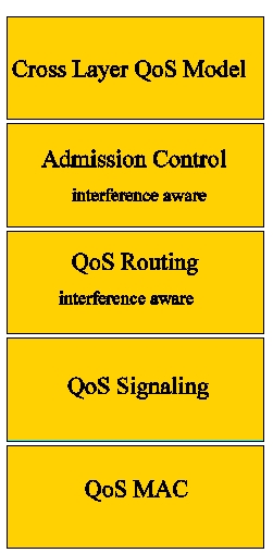
Page 63 In the state of the art, we can identify five building blocks, also called QoS components, in order to support QoS management in a MANET. These five building blocks are illustrated in Figure 3. Figure 3: QoS architecture We now briefly define each of them:
In the following, we focus more particularly on two types of flows: We assume that the bandwidth Bf requested by a flow f is expressed at the MAC level. The reader interested can refer to [Nguyen and Minet 2005a] for a model translating a bandwidth request expressed at the application level into a bandwidth request expressed at the MAC 802.11b level. In this paper, we also assume that interferences are limited to two hops. Page 64 If there is not enough resources to accept the new QoS flow, this flow is rejected. As previously said in Section 1, QoS routing and admission control must be interference-aware. In order to protect QoS flows from interferences created by BE flows, a leaky bucket is introduced to shape the BE packets sent or forwarded by this node. This will be developed in Section 3.5.
As QoS routing is invoked upon any topology change, a simple algorithm must be chosen: its complexity must be similar to Dijkstra's one. The shortest routes (minimum hop count) tend to minimize the network resources used for the transmission of a packet from its source to its destination. Therefore, the hop count metrics must be taken into account. As some flows have bandwidth requirements, the bandwidth metrics must also be considered. Radio interferences should be taken into account. Consequently, QoS routing must select the shortest route (minimum hop count) providing the requested bandwidth. If several routes exist, the route with the widest available bandwidth is chosen. Such an algorithm is called the widest shortest path algorithm. Moreover, as OLSR is the routing algorithm chosen and resources are limited in MANETs, the QoS routing interference-aware algorithm should keep the optimisations present in OLSR. The optimization of this link state routing for MANET relies on the concept of multipoint relays. Interference-aware QoS routing must find the shortest path meeting the bandwidth requested using the partial topology knowledge provided by OLSR, in which the MPRs selection has been changed to take into account the bandwidth metrics. We will wee in Section 6.1 how this solution adapts to traffic and topology changes. Page 65 3.2 QoS signalingTo select the route meeting the bandwidth required, the routing protocol must know the bandwidth locally available at each node. QoS signaling is introduced for this purpose. QoS parameter values are disseminated in the network by means of MPRs. The selection of MPRs is modified to consider the bandwidth locally available at each node. The main drawback of this solution lies in the overhead generated: each flooded message leads to a number of retransmissions higher than that obtained with native OLSR. In this paper, we show how to reconcile the optimized performances of MPR flooding with QoS support. For this purpose, we distinguish two types of MPRs:
3.2.1 Measure of the Local Available BandwidthThe Local Available Bandwidth (LAB) of a node is measured locally at the MAC level. This measure can be deduced from the QoS parameters values given by the MAC driver if they are available. The LAB can also be deduced from the load submitted by nodes up to two hops from the node considered. 3.2.2 Dissemination of the local available bandwidthThe local available bandwidth is disseminated locally by means of Hello and globally by means of TC messages. More precisely:
Notice that according to OLSR rule, only MPRF nodes of the sender retransmit the received message and only if they receive it for the first time. 3.3 MPR selectionTwo MPR selections are done by each node: Page 66
Figure 4.a illustrates the selection of MPRF done by node A. Node A selects node C as its unique MPRF to reach its two-hop neighbors D, E and F. Assuming that the local available bandwidth is equal to 5Mbps on node B and 1Mbps on node C, then node A selects as its MPRBs:
Figure 4: Selection of MPRs by node A.
3.4 QoS routingQoS routing is achieved by means of the widest shortest path algorithm. The routing algorithm differs according to the class of the flow: QoS flow or BE flow. Page 67 3.4.1 QoS routing of BE flowsQoS routing of BE flows is unconstrained; it aims at providing the widest shortest path between any two nodes (i.e. the path with the minimum hop number and in case of equality, the path with the largest available bandwidth). It is the default algorithm used to compute the routing table. The one-hop neighbors and two-hop neighbors are put in the routing table. The first ones can be accessed directly. The second ones are accessed via their MPRBs. If for a two-hop neighbor, there are several MPRBs, the one with the largest LAB is selected to reach this neighbor. All nodes that have as MPRB a two-hop node are then put in the routing table. If for such a node, there are several MPRBs, the one with the largest LAB is selected to reach this node. This process is repeated until all nodes are inserted in the routing table. This algorithm is called whenever there is a change in the one-hop neighborhood, two-hop neighborhood or topology table. BE flows are routed hop by hop. When a BE packet is received by a node that is not its destination, it is forwarded hop by hop according to the local routing table. 3.4.2 QoS routing of QoS flowsQoS routing of QoS flows is constrained by a bandwidth request. It is used to compute a route offering the requested bandwidth to reach the destination. All nodes whose local available bandwidth is smaller than the requested bandwidth and all nodes in the interference area of such transmitter nodes are temporarily removed from the one-hop and two-hop neighborhood and the topology tables. The widest shortest path algorithm is then applied with these updated tables. This algorithm is called by the admission control for a QoS flow, which is periodically invoked in order to keep the shortest path providing the requested bandwidth to reach the destination. The path obtained by this algorithm is then included by the source in each packet of the QoS flow and source routing is then applied. When a QoS packet is received by a node that is not its destination, it is forwarded by the IP layer according to the source routing option in its IP header. We will see in section 6.3 that source routing provides more stable routes than hop by hop routing. 3.5 Admission controlIn order to avoid message exchanges, the admission control of a QoS flow is performed locally by the source. It is done periodically in order to optimize resource utilization. A periodic computation of the route followed by a QoS flow allows the use of the shortest route providing the requested bandwidth to reach the destination and consequently allows to spare bandwidth, as we will see with the scenario described in Section 6.1. The admission control calls the QoS routing for the involved QoS flow. BE flows are shaped by a leaky bucket. The purpose of this leaky bucket is to limit those flows so that their resource utilization does not affect the resources granted to QoS flows. Page 68 We use a leaky bucket at each node to adjust the output rate of the BE traffic forwarded or generated by this node. The output rate of a BE traffic at a node N must not exceed M2LAB, the minimum LAB value of nodes in its interference area, (see Section 3.2.2). This amount of bandwidth available at N must be shared by all nodes in its interference area. Moreover, when a collision occurs, the MAC layer retransmits the colliding packet until it is correctly received. This leads to the chickenand-egg problem: when the amount of bandwidth available at a node decreases, there are potentially more collisions. And when a collision occurs, there are less available bandwidth because the bandwidth consumed is multiplied by the number of retransmissions. Therefore, we use the following formula to adjust the output rate of the leaky bucket, denoted r, at node N: 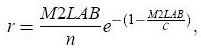 where C is the medium capacity (i.e. 11Mbps with 802.11b) and n is the number of nodes in the interference area of node N that forward the same BE traffic. In this paper, we consider that each BE flow at a node N is forwarded by at least three nodes in the interference area of N: one node before N, node N and one node after N. Thus, we use n = 3. We will see in Section 6.2 the benefits brought by the leaky bucket. 4 Flooding optimization with MPRFs and MPRBsWe now compare the performance, in terms of flooding optimization, of:
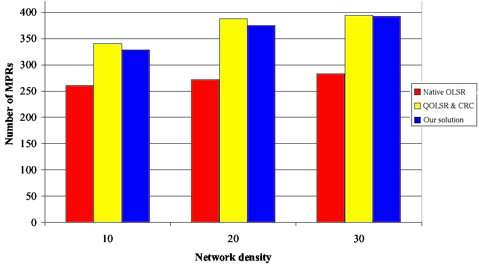
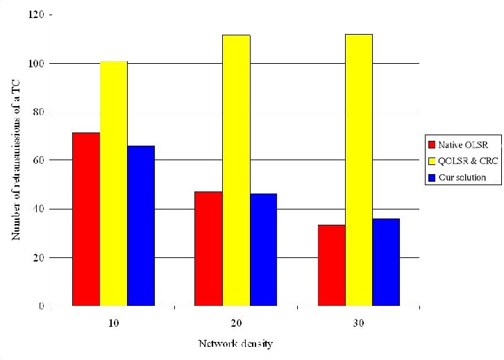
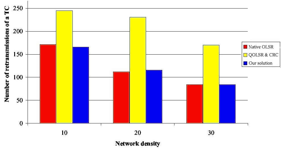
This comparison validates our design choice: i.e., to distinguish MPRs used for flooding from those used for building routes. 4.1 Models and simulation parametersThe simulations are performed with NS-2. The models and parameters given in this subsection are used throughout this paper. According to the default value of NS-2, the reception range of a node is 250m and the carrier-sense range is 550m. We use the IEEE 802.11b MAC protocol without RTS/CTS. The nominal bandwidth is 11Mbps. OLSR parameters are set as recommended in [Adjih et al. 2003]: the Hello period is 2s and the TC period is 5s. Page 69 4.2 Simulation resultsWe consider two network configurations: one with 200 nodes and another with 400 nodes. In both configurations, the network density varies from 10 to 30 neighbors per node. Definition 3. The network density can be defined as the average number of one-hop neighbors per node. It is equal to the total number of nodes in the MANET times πR2 divided by the network area, where R is the radio transmission range. More precisely, the number of nodes in a configuration is kept constant, whereas the size of the square varies in order to get the desired density. No user flow is introduced. Figures 5 and 6 show that our solution generates a number of MPRs lightly smaller than QOLSR and the CRC solution. This number is in any case higher than the number of MPRs generated by classical OLSR. The increase in the number of MPRs generated by any solution supporting QoS is needed in order to be able to provide the shortest path with the widest available bandwidth. The small benefit brought by our solution compared to QOLSR and the CRC solution can be explained by the fact that flooding is optimized, leading to less TC retransmissions (as we will see in the next paragraph) and hence a smaller probability of Hello loss. Figure 5: Number of MPRs with 200 nodes. Page 70 Figure 6: Number of MPRs with 400 nodes. We now study the flooding of a TC message in the network and focus on the number of retransmissions of this message. Indeed this number of retransmissions is undergone by any message flooded in the network such as gateway advertisement and service announcement. Figures 7 and 8 show that the retransmission number of a TC is higher with any solution using MPRB for flooding, like QOLSR and the CRC solution, than with our solution and classical OLSR. Moreover, our solution generates the same number of TC retransmission per TC generated as classical OLSR. Consequently, our solution offers the same optimization degree with regard to flooding as classical OLSR. Figure 7: Number of retransmissions per TC with 200 nodes. Page 71 Figure 8: Number of retransmissions per TC with 400 nodes. In conclusion, we observe that our solution generates the same number of MPRs as the CRC one [Ge et al 2003] and QOLSR [Badis and Al Agha 2005]. This is needed to select the shortest route offering the requested bandwidth. Moreover, the number of MPRBs can reach:
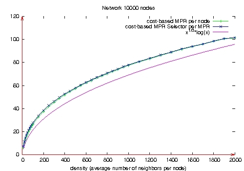
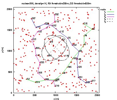
Moreover, our solution generates the same number of retransmissions per message broadcast in the MANET as native OLSR. 5 Control message overheadIn this section, we evaluate the overhead induced by the QoS support in terms of control messages. Notice that this QoS support does not require any additional control message. The Hello message contains the QoS parameter (the LAB) of each neighbor, in addition to its link status. Regarding TC messages, we now compare their size in native OLSR and in our solution. This size is the same for QOLSR, the CRC solution and our solution, as these three solutions use the same algorithm to select the MPRBs. As the size of a TC message originated from a node N is equal to a constant plus a size proportional to the number of MPRB selectors of N, we compare the average number of MPRB selectors per MPRB in our solution with the average number of MPR selectors per MPR in native OLSR. Figure 9 depicts these average numbers for different network densities in a network of 10,000 nodes. It follows that the average number of MPR selector per MPR in native OLSR is in the order of O(M1/3), where M is the average number of neighbors per node, as proved in [Jacquet et al. 2001]. In [Nguyen et Minet 2006], we show that the average number of MPRB selector per MPRB is in the order of O(M1/3log(M)), as shown in Figure 9. Page 72 In our solution, the TC message includes for each MPRB selector declared in the TC message, its QoS parameter (the LAB), as done with the Hello messages. Figure 9: Number of MPR selectors per MPR. 6 Performance evaluation in static configurationsIn this section, we report performance evaluation of our solution in static configurations. Mobility is studied in Section 7. The purpose of this performance evaluation is to validate the choices we made during the design of our solution and to evaluate the benefits brought by this QoS support. 6.1 Adaptation of QoS routes to traffic and topology changesWe first consider a network of 300 nodes and a network density of 14. In the first scenario, characteristics of users flows are defined in Table 1, as well as the loss rate obtained by each of them. In this scenario, BE flows are introduced to saturate the network and not to be compared with QoS flows. Comparisons will be done in the next scenarios. Page 73
Table 1: 3 QoS flows and 2 BE flows. This scenario shows that:
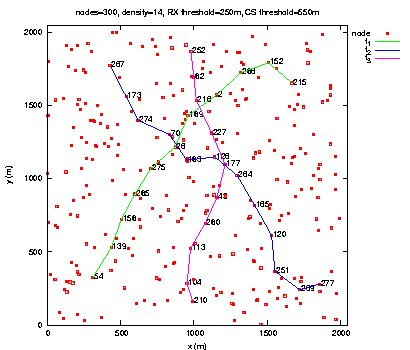
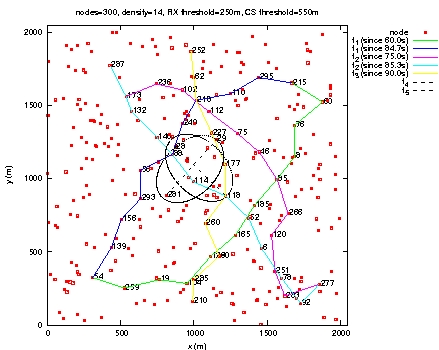
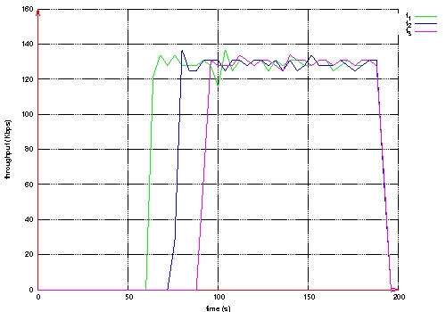
Figure 10: Throughput measured at the destination of each QoS flow. Page 74 Figure 11: Routes taken by QoS flows during BE flows activity. Figure 12: Routes taken by QoS flows after BE flows halt. Page 75 The second scenario is the same as the previous one, except that Best Effort flows are shaped by a leaky bucket. Packets having no token are rejected. Here, we notice in Figure 13 that QoS flows do not wait until the end of Best Effort flows to choose shorter routes. The loss rate is smaller for QoS flows than in the previous scenario as shown in Table 2. The throughput measured at the destination of each QoS flow is more stable (see Figure 14). Figure 13: Routes taken by QoS flows during BE flows activity. Figure 14: Throughput measured at the destination of each QoS flow. Page 76
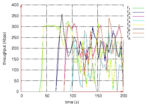
Table 2: 3 QoS flows and 2 BE flows. 6.2 Protection of QoS flows against Best Effort flowsWe now focus on a network of 200 nodes and a density of 10. In the third scenario, eight BE flows are considered as defined in Table 3. Each pair (source, destination) is shared by two flows. The loss rate and the throughput measured at the destination of each flow is given in Table 3 and Figure 15, respectively. They are clearly unacceptable. Table 3: 8 BE flows. Figure 15: Throughput measured at the destination of each BE flow. Page 77 In this fourth scenario, four flows are QoS flows and the other four are BE. The BE flows are not ruled by a leaky bucket. We observe in Table 4 that the admission control rejects two QoS flows because of the lack of bandwidth resources: flows f3 and f4. The delivery rate obtained by QoS flows is lightly higher than that obtained by BE flows. These simulation results justify the choice that both admission control and QoS routing should be interference-aware. We will see in the next scenario how the leaky bucket shaping the BE flows can improve this rate. The throughput obtained by each flow is depicted in Figure 16. Table 4: 4 QoS flows and 4 BE flows.
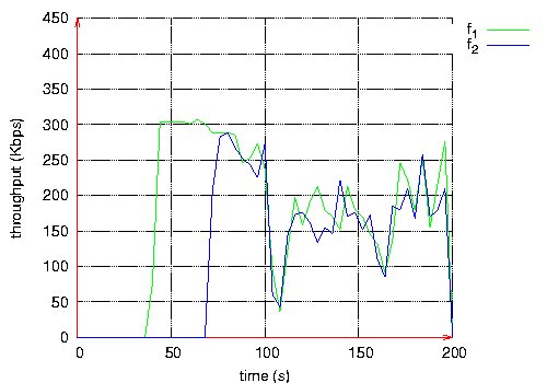
Figure 16: Throughput measured at the destination of each flow. The fifth scenario is identical to the previous one except that a leaky bucket is introduced to shape BE flows. The loss rate is given by Table 5. We notice a dramatic decrease of loss rate (divided by 10) for QoS flows. In the same way, the throughput obtained by each flow, depicted in Figure 17, is more stable than in the previous scenario. This shows the benefit brought by the leaky bucket introduction. Page 78 Table 5: 4 QoS flows and 4 BE flows. Figure 17: Throughput measured at the destination of each BE and QoS flow. The results obtained in these three scenarios show that QoS flows are favored with regard to BE flows. Indeed, they have a much higher delivery rate and a throughput close to that requested. All simulation results reported in this section justify the design choices we made. 6.3 More stable routes for QoS flowsWe consider a network of 200 nodes and a density of 10. In the sixth scenario, we have 4 QoS flows and 4 BE flows with leaky bucket and source routing is used for QoS flows as said in Section 3. The loss rate is given in Table 6. The throughput obtained by each flow is depicted in Figure 18. These values are very good for QoS flows. Page 79 Table 6: 4 QoS flows and 4 BE flows. Figure 18: Throughput measured at the destination of each BE and QoS flow. Page 80 The seventh scenario is identical to the previous one, except that source routing is not used for QoS flows. The loss rate is given in Table 7. The throughput obtained by each flow is depicted in Figure 19. In this scenario, QoS flows obtain results worse than in the previous scenario. Table 7: 4 QoS flows and 4 BE flows. Figure 19: Throughput measured at the destination of each BE and QoS flow. No route change is observed for QoS flows in the sixth scenario where source routing is used whereas in the seventh scenario, QoS flows are rerouted several times. This experiment shows the interest of source routing against hop-by-hop routing. Page 81 6.4 ConclusionWe observe that with this solution:
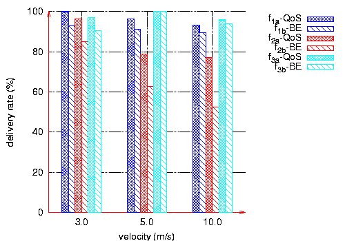
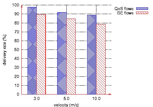
We can conclude that this solution highly improves the QoS perceived by the user. 7 Performance evaluation with mobilityIn this section, we study the behavior of our solution in the presence of mobility. In all the simulations reported, the mobility model chosen is the random waypoint. Each node randomly selects a destination and moves at a speed chosen between 0 and a maximum speed (3m/s, 5m/s, 10m/s or 20m/s). Once the node reaches that destination, it repeats the move for another random destination. There is no pause time between two moves. All simulations last 300s. We first study in Subsection 7.1 the QoS obtained by both QoS and BE flows when the velocity increases: 3m/s, 5m/s and then 10m/s. In Subsection 7.2, we focus on high mobility with a velocity of 20m/s. 7.1 Impact of the velocity on the delivery rateIn this series of simulations on mobility, we consider a network of 100 nodes and a density of 20. The OLSR protocol configuration is as recommended in [Adjih et al. 2003]. We consider six CBR flows at 128 kbps. Three are BE flows and three are QoS flows. Each QoS flow has the same pair (source, destination) as a BE flow. We evaluate the delivery rate of each flow at its destination for different velocities: 3m/s, 5m/s and 10m/s. Page 82 Figure 20 shows that for the three velocities, QoS flows receive a higher delivery rate than BE flows, and their throughput is more stable. However, QoS support does not prevent a decrease in the delivery rate when the velocity increases. This is due to the fact that when velocity increases in this mobility model, all links break very often. The main reason for losing a packet is then a broken link. QoS support does not help to recover more quickly from broken links.
Figure 20: Delivery rates versus velocities. The throughput obtained at the destination is more stable for the QoS flows as illustrated by Figure 21.
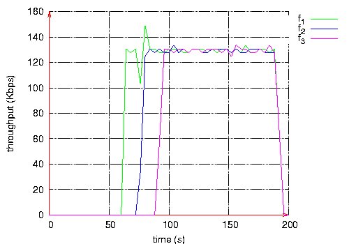
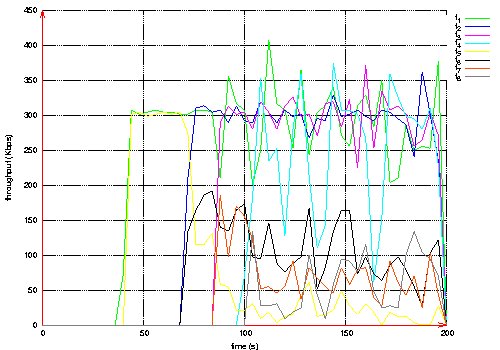
Figure 21: Throughput measured at destination of each QoS and BE flows, velocity 10m/s. Page 83 7.2 High mobilityWe consider a network of 50 nodes and a density of 10. In this scenario, the velocity is 20m/s. Notice that for this velocity, OLSR configuration parameters are made shorter: 1s for the Hello period and 2.5s for the TC period. Three QoS flows and three BE flows are considered. The three QoS flows have the same characteristics as the three BE flows, one by one: same source and destination, same start and stop time. All flows are CBR at 128 Kbps. Figure 22 depicts the delivery rate obtained by QoS flows and BE flows, whereas Figure 23 depicts their respective throughput.
Figure 22: Delivery rates at 20m/s.
Figure 23: Throughput measured at destination of each QoS and BE flows, velocity 20m/s. Page 84 This last scenario shows that the three QoS flows receive a better QoS than BE flows:
8 ConclusionAs in a wired network, QoS support in a MANET is required by more and more applications. We assume here that an application expresses the QoS it requires in terms of bandwidth. As radio interferences strongly affect the bandwidth offered to users, they must be taken into account in the bandwidth management. As QoS support implies to select MPRs according to their local available bandwidth, it leads to a number of MPRs per node higher than that obtained with the native version of OLSR. Consequently, the efficiency of flooding is reduced. In this paper, we have shown how to reconcile an interference-aware QoS support with an efficient flooding. Our solution distinguishes two types of multipoint relays: those in charge of MPR flooding that are selected as specified in the classical OLSR version and the others that are used to select routes, considering bandwidth demand and interferences. Simulation results have shown that with the proposed solution, routes are more stable and accepted flows receive the bandwidth they have requested. Moreover, the overhead due to this QoS support, is kept low and flooding achieves the excellent performances as in the native version of OLSR. This solution also achieves good performances in case of mobility. For high mobility, the benefit brought by this solution still exists but is less important. In all the other cases, the QoS perceived by the users is largely improved. References[Adjih et al. 2003] Adjih C., Clausen T., Jacquet P., Laouiti A., Minet P., Muhlethaler P., Qayyum A., Viennot L.: Optimized Link State Routing Protocol, RFC 3626, IETF, 2003. [Ahn et al. 2002] Ahn G.-S., Campbell A., Veres A., Sun L.-H., SWAN: Service Differentiationin stateless Wireless Ad hoc Networks, INFOCOM'2002, New York, New York, June 2002. [Allard et al. 2004] Allard G., Georgiadis L., Jacquet P., Mans B.: Bandwidth Reservation inMultihop Wireless Networks: complexity, heuristics and mechanisms, International Journal of Wireless and Mobile Computing (inderscience), accepted for publication in May 2004, Toappear (ISSN-1741-1084). [Badis et al. 2004] Badis H., Munaretto A., Al Agha K., Pujolle G.: Optimal Path Selection on a Link state QoS Routing, VTC'2004 Spring, Milan, Italy, May 2004. [Badis and Al Agha 2005] Badis H. and Al Agha K.: QOLSR, QoS routing for Ad Hoc WirelessNetworks Using OLSR, in European Transactions on Telecommunications, vol. 15, nffi 4, 2005. [Chaudet and Guerin-Lassous 2002] Chaudet C., I. Guérin-Lassous: BRuIT: Bandwidth Reservation under InTerferences influence, in European Wireless (EW), pp. 466-472, 2002. [Ge et al 2003] Ge Y., Kunz T., Lamont L.: Quality of Service Routing in Ad hoc Networks Using OLSR, HICSS'03, Big Island, Hawai, January 2003. [Jacquet et al. 2001] Jacquet P., Laouiti A., Minet P., L. Viennot: Performance analysis of OLSR Multipoint Relay flooding in two ad hoc wireless network models, INRIA ResearchReport 4260, http://www.inria.fr/rrrt/rr-4260.html, September 2001. [Lee et al. 2000] Lee S-B., Ahn G-S., Zhang X., Campbell A.T.: INSIGNIA: An IP-BasedQuality of Service Framework for Mobile ad Hoc Networks, in Journal of Parallel and Distributed Computing, nffi60, pp. 374-406, 2000. [Mans and Shrestha 2004] Mans B., Shrestha N.: Performance Evaluation of Approximation Algorithms for Multipoint Relay Selection, Med-Hoc-Net 2004, Bodrum, Turkey, June 2004. Page 85 [Nguyen and Minet 2005a] Nguyen D-Q., Minet P.: Evaluation of the Bandwidth Needed at the MAC 802.11b Level, INRIA research report, No5553, April 2005, INRIA Rocquencourt, France. http://www.inria.fr/rrrt/rr-5553.html [Nguyen and Minet 2005b] Nguyen D-Q., Minet P.: Interference-aware QoS OLSR for mobile ad hoc network routing, int. Workshop on Self-Assembling Wireless Networks,SAWN'2005, Maryland, USA, May 2005. [Nguyen et Minet 2006] Nguyen D., Minet P.: Analysis of Multipoint Relays Selection in theOLSR Routing Protocol with and without QoS Support, INRIA Research Report 6067, http://www.inria.fr/rrrt/rr-6067.html, December 2006. [Nikaein and Bonnet 2004] Nikaein N., Bonnet C.: A Glance at Quality of service Models for mMobile Ad Hoc Networks, http://www.eurecom.fr/~nikaeinn/qos.pdf, 2004. [Qayum et al.2000] Qayyum A., Viennot L., Laouiti A.: Multipoint relaying: An efficient technique for flooding in mobile wireless networks, Research Report no3898, INRIA Rocquencourt, France, March 2000. [Xiao et al. 2000] Xiao H., W.K. Seah , Lo A., Chua K.C.: A Flexible Quality of service Modelfor Mobile ad hoc networks, IEEE VTC'2000 Spring, Tokyo, Japan, May 2000. Page 86 |
|||||||||||||||||||||||||||||||||||||||||||||||||||||||||||||||||||||||||||||
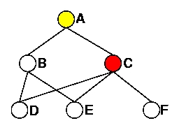 (a) MPRFs of A
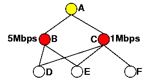 (b) MPRBs of A
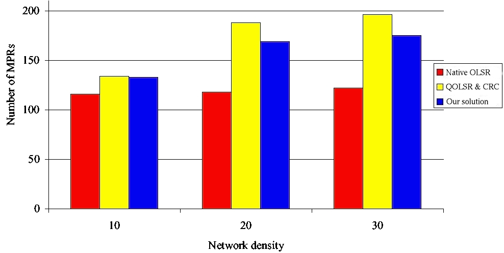
 (a) QoS Flows
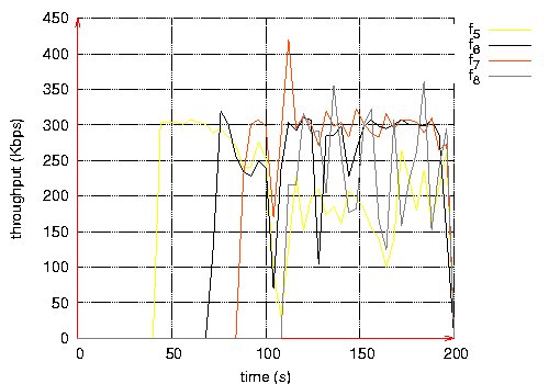 (b) BE Flows
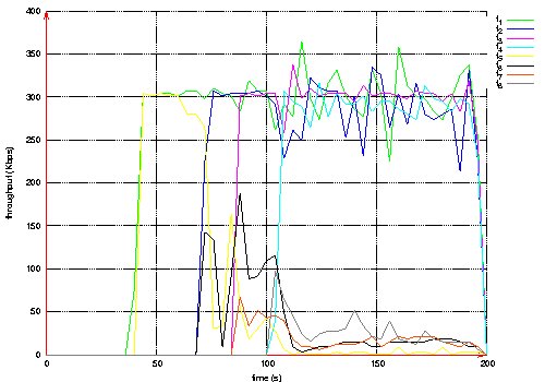

 (a) Each flow
 (b) Average
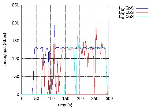 (a) QoS flows
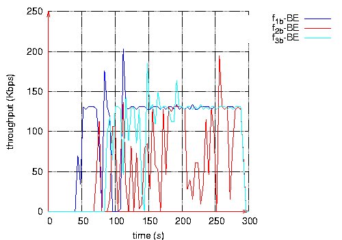 (b) BE flows
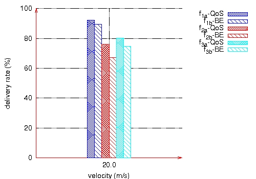 (a) Each flow
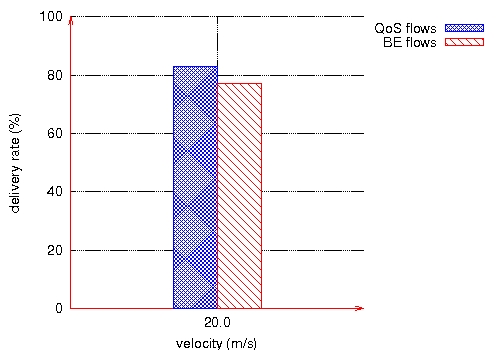 (b) Average
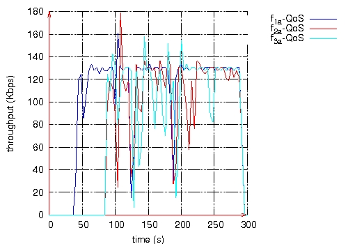 (a) QoS flows
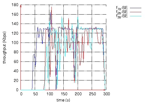 (b) BE flows