| Submission Procedure |
Analyzing the Light Control System with PVSAdriaan de Groot1 Jozef Hooman Abstract: The interactive theorem prover PVS is used to formalize the user needs of the Light Control system. First the system is modeled at a high level of abstraction, in terms of properties the user can observe. After resolving ambiguities and conflicts, a refinement is defined, using dimmable light actuators. Correctness of the refinement has been proved in PVS, under the assumption that there are no internal delays. Next these internal delays are taken into account, leading to a new notion of delay-refinement which allows abstraction from delays such that systems with delays can be seen as an approximation of an undelayed specification. Keywords: Requirements engineering, specification, PVS Category: D.2.1 1 IntroductionIt is known from the literature that errors in a requirements specification propagate through all phases of the design; they are often difficult to detect and costly to repair (see, e.g. [Rus93, Som92]). The general aim of our work is to investigate how the quality of the requirements specification can be improved, especially focusing on embedded systems. Formulating the requirements of a complex embedded system, including timing requirements, is far from trivial. Often these specifications are ambiguous, incomplete, or even inconsistent. To obtain unambiguous requirements, we propose to formalize the requirements in formal language, that is, a language with a precise mathematical meaning. This also enables formal analysis of the specification to detect errors and inconsistencies and a formal proof of consistency. Moreover, subsequent refinement and design steps can be proved correct in a formal, mathematical way. Our approach is motivated by three points that we consider to be important for a successful formalization of requirements.
1Supported by a grant from the ICT Group, the Netherlands Page 621 analysis back to the informal formulation such that they can be discussed with domain experts. After consulting these experts, the incorporation of their solutions in the formal specification is rather straightforward. Moreover, by having a close connection with the informal specification, validation of the formal specification (does it capture the requirements we really need?) becomes easier, see e.g. [Wup98].
This article uses the Light Control Case Study [PD00] as a vehicle to demonstrate our approach to requirements specification for complex embedded systems. In this case study the illumination of rooms is specified based on settings of users and (re)occupancy of rooms. To realize the required illumination, there are sensors (e.g. to detect whether rooms are occupied and to measure the outdoor light) and actuators (there are two dimmable ceiling light groups in a room). Page numbers in the text of this article refer to the pages of the informal specification [PD00]. U1, U2, etc. refer to the user needs on p. 9. Q1, Q2, etc. refer to the list of questions-and-answers, also available on the web site for [PD00]. We base our specification on the original informal specification and the answers to questions Q1Q46 (the state of a airs as of December 15th 1999). More questions were asked, but we decided not to try to adapt our specification to every change. This does not appear to have been detrimental, although Q58 does add information that makes some of our assumptions untrue (see section 4.1). To high-light the essential points of our approach, we did not formalize the whole specification, but focussed on the user needs for rooms and the dimmable lights. 1.1 Terminology and Formalization ApproachA system is a black box that can be distinguished from its environment.
We can only observe the exterior of a system which has a finite number
of ports. Let L denote the set of ports. The system interacts
with its environment through these ports, and only through the ports. Interaction
in this case means exchanging values. Each port has an associated port-type
which can be any data type, although simple data types (integers, booleans,
records over these types) are commonly used. The number of ports of a system
is fixed (i.e. |L|) and there is some fixed data type Tp
for each port p We partition the ports of a system into two disjoint sets: the input
ports Li and the output ports Lo.
We write I for the type of tuples over the types of the input ports (i.e.
Since we are dealing with real-time-systems, we need some notion of
time (see e.g. [vT94, Koy91] for
an overview). For the purpose of this article, we model time with the real
numbers. At each instant in time we can observe a system and record a so-called
observation, which is a tuple of length |Lo| of
type Page 622 We formalize the informal specification using the following approach.
1.2 Iterative ApproachIn the Light Control Case Study, we proceed through three steps that represent a typical iterative approach to formal requirements engineering of embedded systems.
Page 623 1.3 Tool SupportOur specifications are formulated in the language of the interactive theorem prover PVS [ORSvH95, PVS99]. The specification language of PVS is a classical, typed higher-order logic with a large number of built-in types (e.g. booleans, integers, reals) and type-constructors (as functions, sets, tuples, records), including a powerful mechanism to define abstract data types. Typechecking PVS specifications is not decidable and the system may require the user to prove so-called Type Check Conditions (TCCs) to ensure type correctness. Specifications can be structured through a hierarchy of parameterized theories. Logical analysis of specifications can be mechanized using the powerful theorem prover of the PVS system. Our choice of PVS is based on earlier experience with this tool, e.g. to model a steam boiler control system [VH96] and to formalize the requirements of a command and control system [vdPHdJ98]. The specification language is very expressive and fairly intuitive, which makes it easy to maintain a close connection with informal text. The fact that the language is strongly typed turns out to be very useful for the early detection of errors. We will explain PVS notation throughout this article, when necessary. Some preliminaries are in order, though. PVS groups definitions, axioms and theorems into theories. A theory has a name, such as system. A minimal PVS theory is system : THEORY BEGIN END system PVS theories may have parameters, which are placed between [] after the theory name. Theories can refer to each other; to import theory system, PVS uses the notation IMPORTING system. 1.4 Formalization with PVSWe show by an example how we model system requirements in PVS. Consider a system with four inputs and two outputs which should satisfy some specification S [see Fig. 1]. The set of ports for this system is L = {I1 . . . I4, O1, O2}. The set of output ports is Lo = {O1, O2}.
Figure 1: A systems with four inputs and two outputs. Page 624 Assume as given a PVS theory systemTypes which defines the type Time and the types T1 through T4 of the ports I1 through I4, respectively. Moreover, output port O1 has type T5, O2 has type T6, and the output type O is the product type T5 x T6. Henceforth we also frequently combine the outputs in a record. The PVS theory system, shown below, first imports theory systemTypes and next contains a list of parameters for the input. PVS uses the syntax [ domain -> range ] to denote functions; a colon : means of-type. Each input port is modeled as a function from Time to the type of the port. Given the inputs, which can be seen as an implicit parameter of all definitions in the theory, the possible outputs of the system are specified by S_predicate. An arbitrary out-put satisfying this predicate is given by instance which is defined as a constant of the type consisting of all output functions satisfying S_predicate. system [ (IMPORTING systemTypes)
I1:[Time->T1], I2:[Time->T2],
I3:[Time->T3], I4:[Time->T4] ] : THEORY
BEGIN
S_predicate : [ [Time->O] -> bool ] = ...
instance : { out:[Time->O] | S_predicate(out) }
END system
A few additional remarks about this theory:
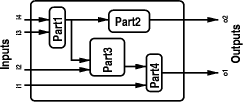
In this style, it is easy to compose a system out of parts that are connected in some way. We simply instantiate the proper input ports of a part with the instance that represents the output of another part. Consider the system in [Fig. 2]. The system as a whole has inputs I1 through I4. These inputs are passed to the theories which specify parts 1, 3 and 4. The outputs of parts 1 and 3 are passed on to other parts. The outputs of parts 2 and 4 are finally declared to be outputs of the system. In the next PVS file this is realized by using an alternative notation for IMPORTING; we use "p1: THEORY = . . . " to import a theory and give it a name (p1) within the theory system. This leads to a theory with the following structure: Page 625
Figure 2: A system composed of parts system [ (IMPORTING systemTypes)
I1:[Time->T1], I2:[Time->T2],
I3:[Time->T3], I4:[Time->T4] ] : THEORY
BEGIN
p1: THEORY = part1[I3,I4]
p2: THEORY = part2[p1.instance]
p3: THEORY = part3[I2,p1.instance]
p4: THEORY = part4[I1,p3.instance]
instance : [Time->O] = LAMBDA (t:Time) :
( p4.instance(t), p2.instance(t) )
END system
Observe the notation LAMBDA (t:Time) for lambda-abstraction, a common way of defining functions. 2 Top-Level FormalizationIn this section we describe our first formalization of a part of the Light Control System [PD00], following the steps described in section 1.1. Instead of formalizing as much as possible of the informal specification, we consider only a part of the specification and investigate formal analysis and refinement steps for this part. We focus on the user needs U1 through U12 (p. 9) that describe the desired amount of illumination in a room. According to p. 5, a room has a two ceiling light groups (window and wall), each with a push button and a dimmer-actuator. Henceforth we refer to these ceiling light groups as dimmable lights. The user can specify so-called light scenes, consisting of a desired ambient light level in the room and how this should be realized using the two dimmable lights (i.e. using one of them or both). There is also a motion detector in each room and a door closed contact; in the current formalization we abstract from them and simply assume we can observe whether a room is occupied or not. Moreover we do not consider the outdoor light sensors here. In a preliminary version, all PVS theories were parameterized by a uninterpreted type Rooms and most definitions contained an argument to identify the room under consideration. Since this parameter did not have any in uence on the definitions, especially because the requirements of rooms are independent, we removed it from the current formalization. So the room under consideration Page 626 is left implicit here. Note that for a proper treatment of hallways sections, which do inluence each other, we would have to reintroduce this parameter. In section 2.1 we start with a PVS theory that introduces a few timing primitives. Basic types to describe light scenes are presented in section 2.2. The inputs and the outputs of the theory containing the user needs are defined in the sections 2.3 and 2.4, respectively. The most important informal user needs are presented in section 2.5. Our first attempt to formalize them can be found in section 2.6. Section 2.7 discusses the remaining user needs. 2.1 Timing PrimitivesSince the user needs refer to periods of time, we start with a PVS theory
that introduces a few basic timing primitives. As mentioned in the introduction,
we use the real numbers to represent physical time. The type real is pre-defined
in PVS, together with the usual operations such as +, , x, TimePrim : THEORY
BEGIN
Time : NONEMPTY_TYPE = real
TimeDuration : NONEMPTY_TYPE = { d:real | d>=0 }
nzTimeDuration : NONEMPTY_TYPE = { d:TimeDuration | d>0 }
Using the reals as a model of time implies that time is dense, so the value of a port might change at any point in time and with arbitrary separation in time. We also introduce functions ms and sec that convert some whole number of milliseconds or seconds into a real value corresponding to the same length of time in the time model. Using functions like ms and sec make the formal specification easier to read for both domain experts and customers. ms(n:nat) : TimeDuration = n sec(n:nat) : TimeDuration = ms(1000*n) END TimePrim 2.2 Light PrimitivesThe PVS theory LightTypes defines the type LightScene as a record containing a desired ambient light level and an option that indicates which of the lights should be used to achieve the desired ambient light level, based on the text on p. 13. In general, records in PVS are of the form [# field1:Type1, ... fieldn:Typen #]. For an element r of this type, both field1(r) and r`field1 can be used to refer to the first field. BoundedLux stems from the informal text on p. 7 describing the external light sensor. Although no mention of bounds is made on p. 13 in the description of light scenes, we assumed that 010000 would be a good range for light scenes. LightTypes : THEORY
BEGIN
IMPORTING TimePrim
Lux : NONEMPTY_TYPE = { n:real | n>=0 }
BoundedLux : NONEMPTY_TYPE = { l:Lux | l<=10000 }
Page 627 SceneOption : NONEMPTY_TYPE = { window, wall, both }
LightScene : NONEMPTY_TYPE =
[# light: BoundedLux, option: SceneOption #]
END LightTypes
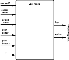
2.3 Inputs to the SystemSince the specification is basically concerned with rooms that are occupied by users, the occupation status of the room under consideration will be given as an input to the system. A room could be considered occupied if the motion detector (mentioned on p. 5 and p. 13) in the room senses motion. We have chosen not to use the motion detectors in this initial specification, since the motion sensors are not part of the user's view of the system. The door-closed contact and the outdoor light sensors have been abstracted away for the same reasons. In PVS theory User Needs parameter occupied? has type [Time->bool]], i.e. a function which expresses whether the room is occupied at each point in time. The other inputs of the system are at least the things that the user can choose, which are described in U9 on p. 9. U9: The room control panel for an office should contain at least: a possibility to set each ceiling light group; a possibility to set the chosen and the default light scene; and a possibility to set T1. Hence the parameters of theory UserNeeds include time-dependent functions that model the chosen scene and the default scene. The clause "set each ceiling light group" is interpreted to mean that the user has push buttons as described on p. 7. This is translated in PVS as the two inputs pushbutton1 and pushbutton2 (they are used in a very limited fashion, namely to indicate that the user has performed some explicit action to choose a light scene). The user can set T1, a period of time which indicates how long a room must remain empty before the control system should take action. It is referred to in U3 and U4 (see section 2.5). Hence theory UserNeeds starts as follows: UserNeeds [ (IMPORTING TimePrim,LightTypes)
occupied? : [Time->bool],
chosen_scene : [Time->LightScene],
default_scene : [Time->LightScene],
pushbutton1 : [Time->bool],
pushbutton2 : [Time->bool],
T1 : [Time->nzTimeDuration] ] : THEORY
Page 627 2.4 Outputs of the SystemThe outputs of the system are the things that the user can actually see. At the highest level, the user needs on p. 9 are concerned with light scenes that should be realized in the rooms. Earlier, in theory LightTypes we already introduced type LightScene to model the things that the user can set, as defined on p. 13 under "light scene". In that definition, light intensities in Lux are stated to vary between 1 and 10000. Note that the light level in a room is potentially Page 628 unbounded, since it may be a very bright sunny day outside and the light level in the room could very well be more than 10000 Lux. The amount of light the lights themselves can produce is never stated in the informal specification. Hence we define a new type roomObservables to model what is actually observed in a room at some point in time. roomObservables : NONEMPTY_TYPE =
[# light: Lux, option: SceneOption #]
roomCharacteristics : NONEMPTY_TYPE = [Time->roomObservables]
Summarizing this and the previous section, [Fig. 3] shows the input and output of the system.
Figure 3: Input and Output of User Needs 2.5 Informal Specification of the User NeedsFor reference, we include the text of the user needs U1U4 from p. 9. The wording of U1 has been changed by Q42, so we quote the modified text here. U1: If a person occupies a room, there has to be safe illumination unless a specific light scene has been chosen or the ceiling light groups are set manually. This means that when the default scene is established (i.e. through U4) and the room is occupied, there must be safe illumination. When the room is occupied and some light scene has been chosen by the user, the lighting must be set according to that scene. U2: As long as the room is occupied, the chosen light scene has to be maintained. Page 629 U3: If the room is reoccupied within T1 minutes since the last person has left the room, the chosen light scene has to be reestablished. U4: If the room is reoccupied after more than T1 minutes since the last person has left the room, the default light scene has to be established. The remaining user needs from p. 9 are discussed in section 2.7. 2.6 First Attempt at FormalizationOur initial attempt concentrated on the specification of the user needs in a naive manner. The initial wording of U1 on p. 9 was sufficiently confusing to require a question (Q42), after which the wording of the user need was amended to its final form as shown in section 2.5. Still later we discovered that this wording still contains some ambiguities, but it sufficed to provide us with a first formula in PVS. As a starting point, we first define a number of variables of type Time. t, t0, t1, t2 : VAR Time A variable declaration in PVS introduces a type for the given variables (i.e. Time for the variable t) so that we do not need to specify the type of that variable in the rest of the theory. Henceforth, we mention variable declarations only once and assume similar declarations in other theories. We start with the formal definition of U1. It states that the illumination in a room has to be safe in certain situations, namely if the default has been established and as long as nothing has been chosen by the user. We interpret this as meaning that when the default is established, the user's choice is "forgotten", so that nothing else is desired. As long as the user makes no choice about the light scene, for example by manipulating the controls for the chosen light scene or toggling the lights, the safe lighting must persist. The default light scene is established under conditions set out in U4. Hence we formalize those conditions first. To formalize the notion of reoccupation, as mentioned in U4, first a few predicates that abbreviate statements about intervals. occupied_until(t) : bool = EXISTS (t0 | t0 < t ) :
FORALL (t1 | t0 <= t1 AND t1 < t) : occupied?(t1)
unoccupied_period(t0,t) : bool =
     FORALL (t1 | t0 <= t1 AND t1 < t) : NOT occupied?(t1)
A room is reoccupied at time t only if the room becomes occupied at t, it was occupied until some moment t0 in the past, and unoccupied between t0 and t. reoccupation_period(t0,t) : bool = t0 < t AND
occupied_until(t0) AND unoccupied_period(t0,t) AND occupied?(t)
With this notion of reoccupied we can define notions reoccupied_withinT1 and reoccupied_longer_thanT1 which state that the previous occupation was at most, respectively more than, T1 time ago. Page 630 reoccupied_withinT1(t) : bool =
EXISTS t0 : reoccupation_period(t0,t) AND t - t0 <= T1(t0)
reoccupied_longer_thanT1(t) : bool =
    EXISTS t0 : reoccupation_period(t0,t) AND t - t0 > T1(t0)
To increase the confidence in the definitions, we have proved that the last two notions are disjoint. The identifier left of the LEMMA keyword is the name of the lemma (disjoint_reoccupation here). This name can be used in proofs to introduce the lemma in a proof of another property. disjoint_reoccupation : LEMMA
NOT (reoccupied_withinT1(t) AND reoccupied_longer_thanT1(t))
When the default has been established, which can now be formalized with the primitives above, we maintain safe illumination as long as nothing has been chosen by the user. To formalize the last clause, we define a function userInputs that provides at each time an observation of the three inputs with which the user can explicitly choose a scene, namely the push buttons and chosen_scene. Any change in these inputs indicates that the user has taken action to choose a specific scene. Changing the default scene parameters is not considered to be an action indicating explicit choice. userInputs(t) : [ bool,bool,LightScene ] =
( pushbutton1(t), pushbutton2(t), chosen_scene(t) )
The following predicate states that no change has occurred in the user's input during the given interval. no_input_change(t1,t2) : bool = t1 <= t2 AND
FORALL (t | t1 <= t AND t < t2) : userInputs(t)=userInputs(t1)
Formula safe_illumination is a straightforward translation of "safe illumination" as stated on p. 13 and used in U1. safe_illumination(l:roomObservables) : bool = l`light>14 Variable roomlight represents the output of the system (i.e. the observed light in a room at any point in time). In our formalization it is restricted by the predicates U1(roomlight) through U4(roomlight). Together they represent the S_predicate for our theory, following the general outline of section 1.1. roomlight : VAR roomCharacteristics After all these preparations we now present our first attempt to formalize U1. U1try(roomlight) : bool = FORALL t : occupied?(t) AND
(EXISTS t1 : t1 <= t AND reoccupied_longer_thanT1(t1) AND
no_input_change(t1,t))
IMPLIES safe_illumination(roomlight(t))
While formalizing this definition, we realized that the specification does not mention the situation when the room was entered the first time, i.e. when there was no previous occupation period. It seems reasonable to have also safe illumination then. Hence we weakened the condition in U1 (i.e. strengthened U1) by removing the periods of occupation which are implied by reoccupied_longer_thanT1. This has been formalized in a convenient predicate called enforce_safety. Page 631 enforce_safety(t) : bool =
EXISTS t0, t1 : t0 + T1(t0) < t1 ANDt1 <= t AND
unoccupied_period(t0,t1) AND no_input_change(t1,t)
Predicate enforce_safety applies to a room if it was unoccupied for a T1 period of time which is sufficient to require the default scene and safety as well and the user subsequently made no explicit choice about the scene. Hence we reformulate U1 as follows: U1(roomlight) : bool = FORALL t : occupied?(t) AND
enforce_safety(t)
IMPLIES safe_illumination(roomlight(t))
Since our previous condition in U1try implies enforce_safety, it is easy to prove that this U1 implies U1try. Note that it depends on the assumptions about the initial value of T1 and how it changes (see also the remarks below after U7) whether this now also imposes a requirement on the light at the first entrance of the room. Compared to all the steps taken for formalizing U1, the formalization of U2 is very straightforward. U2(roomlight) : bool = FORALL t : occupied?(t)
IMPLIES roomlight(t)=chosen_scene(t)
Considering the informal formulation of U1 through U4 (see section 2.5), it is important to mention that we have chosen a meaning for "maintains" and "established" as follows: Maintain: To maintain a light scene, the light scene must be established at all moments within the interval over which the scene must be maintained. Establish: To establish a light scene in a room, the selected light groups (as indicated by the option of the light scene) should be used to augment the outdoor illumination of the room such that the total amount of illumination is per the light scene. Our definition of "establish" refers to outdoor illumination; since we have abstracted away the outdoor illumination we interpret "to augment the outdoor illumination of the room" as "to produce light". Since we already formalized the notion of reoccupation, U3 and U4 can be formulated easily. U3(roomlight) : bool = FORALL t : reoccupied_withinT1(t)
IMPLIES roomlight(t)= chosen_scene(t)
U4(roomlight) : bool = FORALL t : reoccupied_longer_thanT1(t)
    IMPLIES roomlight(t) = default_scene(t)
Page 632 2.7 Analysis of U5-U8Above we have considered user needs U1U4 and U9 (to determine the input). We examine the user needs U5U8 in short, to convince ourselves that they have been sufficiently addressed and that we have not missed any important part of the informal specification. U5: For each room, the chosen light scene can be set using the room control panel. U6: For each room, the default light scene can be set by using the room control panel. Requirements U5 and U6 are reflected in the inputs to the system, although we do not model how or where the user can make such a change. They are also restated in U9. U7: For each room, the value T1 can be set by using the room control panel. Allowing the user to change T1 makes it an input to the system instead of some constant (as we did in a preliminary attempt, not shown here). This time-dependent input makes it somewhat more complicated to find out when a room is reoccupied after T1 time since we do not know which value of T1 to use (it can change after all). In our definition of enforce_safety we chose to use the value of T1 at the beginning of a period of unoccupation as the duration required to enforce safety, as opposed to the value of T1 at the moment of reoccupation. If T1 cannot change while the room is unoccupied this distinction is not important, but we have not assumed this here. U8: If any outdoor light sensor or the motion detector of a room does not work correctly, the user of this room has to be informed. Since we are not concerned with sensors at this level of abstraction, and certainly not with defective sensors, we leave this requirement out. Note that user needs U10U14 refer to particular kinds of rooms and we have decided to concentrate on general rooms here. Finally, we list a number of detailed observations or choices that have been made in the current formalization.
Page 633
3 Analysis of the RequirementsAnalyzing the formal specification of the user needs, we identified three conflicts. They are described in section 3.1. An improved formalization, avoiding these conflicts, is presented in section 3.2. 3.1 ConflictsThe formalization as presented in section 2.6 has a number of conflicting requirements within the specification itself. A conflict arises when there is a situation in which several user needs impose a requirement on the desired light in the room. The following fact illustrates a con ict with U1 and U2. Note that PVS has a number of synonyms for things-that-need-to-be-proved such as LEMMA, THEOREM, and FACT. The different names are meant for the human reader. Recall that U1U2conflict is the name of the property. U1U2conflict : FACT U1(roomlight) AND U2(roomlight) AND
occupied?(t) AND enforce_safety(t)
IMPLIES chosen_scene(t)`light>14
When the room is occupied and safety is enforced then both U1 and U2 apply and the chosen scene must realize an ambient light level that is safe (i.e. greater than 14 Lux). This imposes a strange restriction on the scenes that can be chosen by the user. A similar conflict exists between U1 and U4: U1U4conflict : FACT U1(roomlight) AND U4(roomlight) AND
occupied?(t) AND enforce_safety(t) AND
reoccupied_longer_thanT1(t)
IMPLIES default_scene(t)`light>14
This implies that the default scene should be safe, although this is not implied by any of the other informal requirements. Since we allow arbitrary user inputs (including an arbitrary default scene), this could lead to a contradiction. Another kind of con ict is embodied in the relationship between U2 and U4. U2 unconditionally states that the chosen scene must be maintained; U4 conditionally states that the default scene is to be established. Since we have assumed that "to maintain" implies "to establish", this is a problem unless the default and the chosen scenes are equal. U2U4conflict : FACT U2(roomlight) AND U4(roomlight) AND
reoccupied_longer_thanT1(t)
IMPLIES chosen_scene(t)=default_scene(t)
Page 634 3.2 Second Formalization, Avoiding ConflictsIn the previous section we have identified three conflicts between the user needs; between U1 and U2, U1 and U4, and U2 and U4. We improve our previous formalization by resolving these conflicts, assuming the informal document intended some implicit priority between user needs. Concerning the U1 - U2 conflict, we assume U1 has priority over U2, since otherwise the whole notion of safety and default scenes becomes irrelevant. In general, we decided that safety, i.e. U1, has absolute priority. Note that this choice depends to some extent on our choice of meanings for "establish" and "maintain" and our resolution of the conflict between U2 and U4, below. As such, other solutions are possible, and it should be noted that the answer to question Q50 (which falls outside of the set of the questions we deal with) states that "light scenes always have priority over safety". Interpreting that answer strictly makes safety completely irrelevant, since there is always a scene (either default or chosen) established when the room is occupied. Since we give priority to U1, U1 is not changed and U2 is reformulated so that it is complementary to U1. This is done by requiring that U2 only specifies the light in the room if safety is not enforced. U2(roomlight) : bool = FORALL t : occupied?(t) AND
NOT enforce_safety(t)
IMPLIES roomlight(t)=chosen_scene(t)
We found no conflict with U3 and hence it is not changed. Concerning U4, we have already solved the conflict between U2 and U4, because we can prove reocc_enforce : LEMMA reoccupied_longer_thanT1(t)
IMPLIES enforce_safety(t)
To solve the conflict between U1 and U4, we apply function makeSafe to ensure that when the room has been unoccupied for at least T1 time, the light is safe. makeSafe(l:LightScene) : LightScene =
IF safe_illumination(l) THEN l
ELSE (# light:=15, option:=l`option #) ENDIF
U4(roomlight) : bool = FORALL t : reoccupied_longer_thanT1(t)
    IMPLIES roomlight(t) = makeSafe(default_scene(t))
This leads to the following predicate on the observed light in the room: allNeeds(roomlight) : bool = U1(roomlight) AND U2(roomlight) AND
U3(roomlight) AND U4(roomlight)
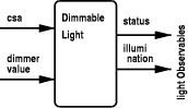
4 Refinement using Dimmable LightsAs a first step towards a realization of the abstract specification of the previous section, we perform a refinement in terms of dimmable lights (which are partly specified in the Light Control Case Study document) and a control system which controls these lights. Page 635 As noted in section 2.6 we have assumed that the meaning of "establish" relates the desired scene to some kind of operations on dimmable lights. Recall that we ignore the outdoor illumination. Hence, the dimmer-actuators on the dimmable lights in the ceiling-light groups are to be set such that the settings of the light realize the desired light scene under certain assumptions about the relationship between the dimmers and the light produced. Refining the specification in terms of a control system and dimmable lights requires specifications of each of these parts, as well as how they work together. Section 4.1 defines the characteristics of a dimmable light in isolation. In section 4.2 we model a component that formalizes our assumptions about the combined e ect of the two dimmable lights in a room on the observed room light. Section 4.3 defines the behavior of the control system for each room. These components are composed in section 4.4 to obtain an undelayed implementation. Then in section 4.5 we demonstrate that this implementation satisfies our formalized user needs. 4.1 Formalizing the Dimmable LightFor the formalization of the dimmable light we used the text and the figure on pp. 78 of the informal specification. Section 2.10 mentions: Inputs to a dimmable light are created by a pulse to toggle the light, by a dimmer to set the current dim value, and by control system active to show the status of the control system. If this signal is not sent every 60 s, the dimmable light switches to fail safe mode, i.e. dim value is assumed to be 100%. Outputs of a dimmable light are generated by a status line to show the current state (on or o ) of the light. One purely textual problem can be identified immediately. On p. 7, the range for a dimmer (which is an input to the dimmable light) is defined as 0-100% while the description of the range mentions only the values 0% and 10-100%. We have assumed that the values 1-9% are also permitted, and that they also produce light. Q58 invalidates this, but as noted in the introduction of this paper, we used only Q1-Q46 for our specification. Also note that introducing a threshold in the dimmers, as done by Q58, it is impossible to realize some scenes that the user may desire, namely those that desire a positive amount of light less than the dimmable lights can produce at a dimmer setting of 10%. Our second choice is somewhat more fundamental. The amount of light the lights themselves can produce is never stated in the informal specification. We have no way of knowing how much light a dimmable light produces. We assume that a dimmable light produces light proportional to its dimmer setting when the light is on, and that a dimmable light can produce anywhere from 0 Lux (o ) to 10000 Lux (fully on, dimmer set to 100%). A third choice is rather pragmatic: we have chosen to drop the pulse and the push button from the light itself. The informal text states: p. 5 . . . push button is pushed: if the ceiling light group is completely
on, it will be switched o ; otherwise it will be switched on completely. Page 636 p. 8 Inputs to a dimmable light are created by a pulse to toggle the light. . . One reason for deleting these two inputs from the dimmable light is that the pulse is supposed to toggle the state of the light from on to o and vice versa, i.e. toggle the status line; the push button is to have a similar e ect. The e ect of the push button appears to vary depending on what kind of room the light is placed in, which makes it unappealing to model it in a generic dimmable light. Another problem is the lack of initial values. Moreover, defining such a toggle function in our dense time model would introduce a lot of technicalities. E.g. we would have to introduce the well-known non-Zeno condition (see, e.g., [AL91]). Hence we decided to let the status line depend on the value of the dimmer only and not be set independently or in uenced by the buttons. The dimmable light is specified in our standard PVS style, as described in section 1.1. First we define in theory LightTypes the types for the input. The input of the control system active (CSA) input line has type ZO which stands for "Zero One", an enumeration type that is different from the booleans. ZO : NONEMPTY_TYPE = { zero, one }
DimmerValue : NONEMPTY_TYPE = { n:real| n>=0 AND n<=100 }
dimmer_on?(d:DimmerValue) : bool = d>0
The theory about dimmable lights is parameterized by functions that give the input values for the light in the course of time. DimmableLight [ (IMPORTING TimePrim,LightTypes)
control_system_active : [Time->ZO],
dimmer_value : [Time->DimmerValue] ] : THEORY
Next, as the output of the dimmable light, we define types for the characteristics of lights. Recall that Lux has already been defined in section 2.2. lightObservables : NONEMPTY_TYPE =
[# status : bool, illumination : Lux #]
lightCharacteristics : NONEMPTY_TYPE = [Time->lightObservables]
Typechecking these definitions leads to a TCC which requires us to prove that the type lightObservables should be nonempty. The proof is trivial, for instance record [# status:=true, illumination:=15 #] is an element of that type. [Fig. 4] depicts the input and output of a dimmable light. First we formalize the fail-safe mode of the light, as mentioned on p. 8: If this (i.e. the control-system-active) signal is not sent every 60 s. the dimmable light switches to fail-safe mode, i.e. dim value is assumed to be 100%. Here "sent" means "received as input by the light." A non-trivial formalization of this condition is given by first rephrasing the informal specification: if the control system is not alive anymore, the dimmable light switches to fail-safe mode. The control system is considered alive if it has sent a control-system-active signal to this light in the past 60 seconds. Formally, Page 637 Figure 4: Input and Output of a Dimmable light alive?(t) : bool = EXISTS t0 : t - sec(60) <= t0 AND t0 <= t AND
control_system_active(t0) = one
We require a period of at least 60 seconds before switching to fail-safe mode. The function failsafe_dimmer uses alive? and the value of the dimmer input to define the actual dimmer value of the light: failsafe_dimmer(t) : DimmerValue =
IF (alive?(t)) THEN dimmer_value(t) ELSE 100 ENDIF
Next we formalize the second choice made at the beginning of this section: the light production of a dimmable light is proportional to the dimmer according to the formula set out above. lightProduction(d:DimmerValue) : Lux = 100 * d The functions defined above are used to define the predicate that characterizes the output of the dimmable light. lc : VAR lightCharacteristics DimLight_predicate (lc) : bool = FORALL t :
LET fd=failsafe_dimmer(t) IN
status(lc(t)) = dimmer_on?(fd) AND
illumination(lc(t)) = lightProduction(fd)
Note the use of a LET construction to introduce an abbreviation. Next we define an instance satisfying this constraint. Recall that (DimLight_predicate) is an abbreviation of {lc | DimLight_predicate (lc) }. instance : (DimLight_predicate) END DimmableLight As mentioned before, typechecking leads to a TCC to show that the type is not empty. Here it is easy to construct an element and show that it satisfies DimLight_predicate: thelc : lightCharacteristics = LAMBDA t :
(# status := dimmer_on?(fd),
illumination := lightProduction(fd) #)
WHERE fd=failsafe_dimmer(t)
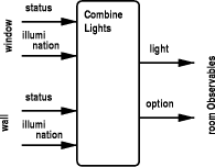
As an alternative to the LET construction, we use a WHERE clause to introduce abbreviation fd in the definition. Page 638 4.2 Combining the LightsSince a room has two dimmable lights we must set both dimmers based on the desired light scene in one single room; this requires a number of assumptions about the behavior of light. Here we assume that the light production of the two lights in a room is summed to find the total light in a room. The two lights contribute equally to the light in a room when both are on. For each light we can discover whether the light is a wall or a window light using the enumeration type LightIds, as defined in theory LightTypes. LightIds : TYPE = { window, wall }
[Fig. 4] shows input and output of a component that formalizes our assumption about the combined light production. This is reflected in the corresponding PVS theory as follows.
Figure 5: Input and Output of the Combine Lights Component CombineLight[ (IMPORTING TimePrim,LightTypes)
dimlight : [LightIds->lightCharacteristics]
] : THEORY
BEGIN
roomlight : VAR roomCharacteristics
The following predicate characterizes the total amount of light (as the sum of the illumination of both dimmers) and the option (i.e. window, wall, or both) using the status of each of the lights. CombineLight_predicate(roomlight) : bool = FORALL t :
LET windowlight = dimlight(window)(t),
walllight = dimlight(wall)(t)
IN
light(roomlight(t)) =
windowlight`illumination + walllight`illumination AND
option(roomlight(t)) =
IF windowlight`status AND NOT walllight`status
Page 639 THEN window
ELSIF NOT windowlight`status AND walllight`status
THEN wall
ELSE both ENDIF
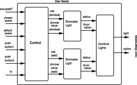
As usual, we define an instance of the room characteristics satisfying this predicate. Also here it is straightforward to prove the generated TCC. instance : (CombineLight_predicate) END CombineLight 4.3 The Control SystemThe control system should calculate dimmer values based on the desired light scene (which may be the default scene or the chosen scene, depending on U3 and U4). It must also provide the other input signals to the two dimmable lights in our case only the control-system-active (CSA) signal, since we have abstracted away the other inputs. Given the specifications of the dimmable lights and the combination of the lights, the aim is to specify a control system such that the implementation depicted in [Fig. 6] is actually a refinement of the user needs. As can be seen from this figure, PVS theory Control has the same parameters Figure 6: Undelayed Refinement of User Needs as theory UserNeeds. We start with the definition of the output type, ControlOutput, which provides the input for each light. Additionally we define a few useful variables. Page 640 ControlOutput : TYPE =
[# control_system_active : [LightIds->[Time->ZO]],
dimmerval : [LightIds->[Time->DimmerValue]]
#]
co     : VAR ControlOutput
li     : VAR LightIds
ls     : VAR LightScene
csa    : VAR [LightIds->[Time->ZO]]
dimval : VAR [LightIds->[Time->DimmerValue] ]
Next we define the CSA signal that our system produces. A real system would assert the signal at certain moments in its control loop as an indication that processing proceeds normally and not assert the signal otherwise. Since we are not dealing with failures here, we simply specify that the CSA-signal is continuously one. csa_predicate(csa) : bool = FORALL li, t : csa(li)(t) = one Next we specify the contribution of dimmer li in the realization of a certain light scene ls. Recall that we assumed that the amount of Lux produced by a single dimmer equals 100 times the dimmer value (see lightProduction in theory DimmableLight). dimmer_part(li,ls) : DimmerValue =
CASES ls`option OF
both : ls`light/200,
window : CASES li OF
window : ls`light/100,
wall : 0
ENDCASES,
wall : CASES li OF
window : 0,
wall : ls`light/100
ENDCASES
ENDCASES
This matches the kind of light wall or window with the desired light scene, and determines the dimmer setting accordingly. Next the dimmer value for each dimmable light is defined by predicate dimval_predicate. It basically applies function dimmer_part to a particular light scene which depends on whether safety is enforced or not. dimval_predicate(dimval) : bool = FORALL li, t :
dimval(li)(t) =
IF enforce_safety(t)
THEN dimmer_part(li,makeSafe(default_scene(t)))
ELSE dimmer_part(li,chosen_scene(t)) ENDIF
Combining the predicates on the output, we can now easily define a particular instance of the control component. Again the TCC is easy to prove. instance : { co | csa_predicate(control_system_active(co)) AND
dimval_predicate(dimmerval(co))}
END Control
Page 641 4.4 Composition of the Undelayed ImplementationIn theory UndelayedImpl we compose the components defined above, according to [Fig. 6]. As the figure shows, the theory has the same input parameters as the theories UserNeeds and Control. Mainly following the pattern described in section 1.4, we import the relevant theories by giving them a name and use typical instances of the output as input to other theories. control : THEORY = Control[occupied?,chosen_scene,default_scene,
pushbutton1,pushbutton2,T1]
windowdimmer : THEORY =
DimmableLight[control_system_active(control.instance)(window),
dimmerval(control.instance)(window)]
walldimmer : THEORY =
DimmableLight[control_system_active(control.instance)(wall),
dimmerval(control.instance)(wall)]
dimlight : [LightIds->lightCharacteristics] = LAMBDA li :
CASES li OF
window : windowdimmer.instance,
wall : walldimmer.instance
ENDCASES
combinedlight : THEORY = CombineLight[dimlight] instance : roomCharacteristics = combinedlight.instance 4.5 Proving Undelayed RefinementIn theory UndelayedRef we prove the undelayed refinement. It has the same parameters as UserNeeds and UndelayedImpl, and imports these two theories as follows. IMPORTING UserNeeds[occupied?,chosen_scene,default_scene,
pushbutton1,pushbutton2,T1]
undelimpl : THEORY =
    UndelayedImpl[occupied?,chosen_scene,default_scene,
                  pushbutton1,pushbutton2,T1]
Now the aim is to prove theorem undelayed_refinement. undelayed_refinement : THEOREM
UserNeeds.allNeeds(undelimpl.instance)
That is, an arbitrary instance of the (undelayed) implementation satisfies the user needs as defined by allNeeds in theory UserNeeds. Our proof consists of several lemmas that state the refinement for each of the user needs. We start with the proof for U1: refineU1 : LEMMA UserNeeds.U1(undelimpl.instance) Page 642 In the interactive proof of this lemma with the PVS proof checker, we first list all available information by introducing the types of the instances and expanding the definitions of all predicates. Next there is a rather mechanic instantiation with the current time point, a further unfolding of definitions and simple rewriting. The next user need, U2, which states that the chosen light scene is maintained while the room is occupied, turned out to be more difficult to handle. If a light scene requires absolute darkness (0 Lux) then both dimmers are set to zero. In the definition of CombineLight_predicate in theory CombineLight we have chosen to identify the situation where both dimmers are set to zero with a light scene option of both. Only during the proof of U2, however, we realized that the chosen light scene can associate any option with a desired illumination of zero. Intuitively we cannot distinguish between darkness realized with one light or two lights. Of course, we could make our definition of CombineLight_predicate less prescriptive, but for simplicity we axiomatically declare here that all dark scenes have option both. LightScenesZero : AXIOM
ls`light = 0 IMPLIES ls`option = both
A straightforward consequence of this axiom is the following FACT. LightScenesProp1 : FACT
ls`option = wall OR ls`option = window IMPLIES ls`light > 0
Using this fact, we can prove that the refined system satisfies U2. refineU2 : LEMMA UserNeeds.U2(undelimpl.instance) While trying to prove that the refined system fulfills our formalization of U3, we discovered that the following situation leads to a conflict. Suppose a user enters a room, sets some chosen scene, and leaves. After more than T1 time has passed, the user returns and does not explicitly request a scene. Because of U4, the default scene is established. After some time, the user leaves and returns quickly in less than T1 time. U3 states that the chosen scene should be reestablished, even though the default scene was established in the meantime. We choose to give U4 priority over U3 in this case; if a room has been empty for a long time, and a user walks in, out and in again without changing any of the settings, the room should still have the default safe lighting. This caused us to add a clause NOT enforce_safety to the definition of U3: U3new(roomlight) : bool = FORALL t : reoccupied_withinT1(t) AND
NOT enforce_safety(t)
IMPLIES roomlight(t)= chosen_scene(t)
But now we observed that U2 implies this new U3 (in fact, this was already the case with our first formalization in section 2.6). U2impliesU3new : LEMMA U2(roomlight) IMPLIES U3new(roomlight) Hence we removed U3 from the user needs, leading to the following definition: allNeeds(roomlight) : bool = U1(roomlight) AND U2(roomlight) AND
U4(roomlight)
Page 643 The proof that the refined system fulfills U4 is straightforward. A trivial combination of the lemmas for U1, U2, and U4 leads to a proof of the final theorem. undelayed_refinement : THEOREM
UserNeeds.allNeeds(undelimpl.instance)
The proof of this theorem - including all of its lemmas such as refineU1 listed above - took us about 150 interactive steps in PVS. 5 Introducing DelaysThus far, only the timing constraints in the requirements have been taken into account in our framework. In the implementation of section 4 the control component calculates dimmer values instantaneously. Moreover, the dimmable lights react instantaneously to the dimmer value and produce an amount of light proportional to the dimmer value. This is not very realistic, since computation is not really instantaneous and the lights have a well defined response time (p. 7 of the informal specification). Hence it seems important to model these internal delays properly. As an example, our next formalization takes one of these delays explicitly into account; in section 5.1 we add a delay to the dimmable lights. In section 5.2 we show that this does not lead to a classical refinement. Still, we establish a formal relation with the undelayed implementation by defining a kind of delay-refinement in section 5.2. 5.1 A Dimmable Light with Response TimeThe informal specification suggests that changing the dimmer value from x to y causes the light to change gradually from producing light proportional to x to producing light proportional to y. It also suggests that the time needed to change is proportional to the difference between x and y. Here we simply assume that the light changes instantaneously from producing light proportional to x to producing light proportional to y at some moment constrained by the maximal delay of dimdelay ms (we use the symbolic constant dimdelay; the informal specification mentions a response time of 10ms). We model a delayed dimmable light by re-using the specification of an undelayed light and applying a delay function to its output. Given a certain delay d, a function f on the time domain is called a delay function if it satisfies the predicate delayFunction? defined below. First we express monotonicity. f : VAR [Time->Time] d, d0 : VAR nzTimeDuration monotonic?(f) : bool = FORALL t1, t2 : t1 < t2 => f(t1)< f(t2) Next we define that function f is a delay function if it shifts time at most d back. We shift time back since the function will be applied to the domain of a characteristic of the system (i.e. a function from the time domain to observables). That is, the new (delayed) output is determined from the original output at a previous time point, at most d time units back. Additionally, we require that f is surjective and monotonically increasing. Page 644 delayFunction?(d)(f) : bool = surjective?(f) AND monotonic?(f) AND
FORALL t : t-d < f(t) AND f(t) <= t
To increase our confidence in the definition we proved a few properties about it. Note that id is the (pre-defined) identity function. dF_injective : THEOREM monotonic?(f) IMPLIES injective?(f) dF_bijective : THEOREM delayFunction?(d)(f) IMPLIES bijective?(f) dF_accepts_longer_delays : THEOREM delayFunction?(d)(f) AND d0>=d
IMPLIES delayFunction?(d0)(f)
dF_id : LEMMA delayFunction?(d)(id)
Next we define a delayed implementation of the user needs. First we import the undelayed implementation and fix a maximal delay and a corresponding delay function. IMPORTING UndelayedImpl[occupied?,chosen_scene,default_scene,
pushbutton1,pushbutton2,T1],
DelayFunctions
dimdelay : nzTimeDuration
delayf   : (delayFunction?(dimdelay))
Then the delayed implementation is defined by simply applying a delay function to the time domain of the output of each dimmer and using that as input for the combined light component. dwindowdimmer_instance : lightCharacteristics =
(windowdimmer.instance) o delayf
dwalldimmer_instance : lightCharacteristics =
    (walldimmer.instance) o delayf
ddimlight : [LightIds->lightCharacteristics] = LAMBDA li :
    CASES li OF
        window : dwindowdimmer_instance,
        wall   : dwalldimmer_instance
    ENDCASES
dcombinedlight : THEORY = CombineLight[ddimlight] instance : roomCharacteristics = dcombinedlight.instance Observe that we have applied the same delays to both failsafe dimmers in the system. In section 6, we discuss the problems that occurs if the delays are not the same. 5.2 Delay-RefinementAlthough these delayed dimmable lights represent a more realistic implementation, for any non-zero delay the delayed implementation does no longer satisfy Page 645 the specification allNeeds. For instance, we cannot guarantee that the chosen scene will be established immediately, as required by our formalization of U2. Hence, also the delayed implementation is not a classical refinement (in the sense of behavior inclusion) of the undelayed one. However, assuming the dimmer delay is relatively small, we still think that the delayed implementation is a reasonable approximation of the undelayed one. The aim is to express this more formally, by establishing some kind of approximation relation between the two. To define a general delay-refinement relation, assume given an arbitrary range R and two functions, concr and abstr from the time domain to R. The relation concr << abstr, denoting that concr is a delay-refinement of abstr, expresses that there exists a delay d such that any abstract value equals a concrete value at a point at most d time units later. concr, abstr : VAR [Time->R] <<(concr,abstr) : bool = EXISTS d :
(FORALL t : (EXISTS t1 : t <= t1 AND t1 < t+d AND
abstr(t) = concr(t1)));
To apply this to the delayed implementation of the user needs, we import this theory using roomObservables instead of the range R. Then we show that the delayed implementation is indeed related to the undelayed one by <<. delayed_ref : THEOREM
DelayedImpl.instance << UndelayedImpl.instance
Observe, however, that the relation << is rather weak and allows for instance a reordering of the output values. Such reorderings are avoided by the delay functions we introduced before, so as a second delay-refinement we relate the two systems by some delay function as well, delaying the abstract undelayed output in such a way that it matches the output of the concrete system with delays. This leads to the delay-refinement relation <= which is shown to be stronger than <<. <= (concr,abstr) : bool =
EXISTS d, (f : (delayFunction?(d))) : abstr o f = concr;
ref_rel : LEMMA (concr <= abstr) IMPLIES (concr << abstr) As expected, in the Light Control Case Study it is easy to prove that the delayed implementation is a delay refinement according to the definition above. delayed_refinement : THEOREM
DelayedImpl.instance <= UndelayedImpl.instance
6 Concluding Remarks6.1 OverviewWe have formalized the user needs of the Light Control Case Study in the specification language of the interactive theorem prover PVS. First, this was done Page 646 on the level of users of the system, in terms of what they can observe. Several problems with the informal specification have been detected and resolved. A few important user needs (U1U4) already gave rise to a large number of questions. Using dimmable light actuators, this specification was refined to a more concrete one. This also demonstrates the consistency of the high-level specification. Such a formal consistency proof turned out to be very useful because it revealed an unexpected conflict. Next we further refined the specification, introducing an explicit delay in the dimmable light. Observing that this does not lead to a classical refinement, we introduced a new notion of delay-refinement and used it to relate the specification with delays to the one without. A PVS dump file with all theories and proofs can be found on http://www.cs.kun.nl/~adridg/lccs/. 6.2 Related WorkRelated to our work are especially other approaches using PVS. The designers of PVS advocate the use of PVS during the early phases of the design of computer systems. For example [Rus97] describes the use of strong type checking, completeness and consistency checking using powerful decision procedures and model-checking of PVS for requirements engineering. This has been applied in several industrial applications. For instance, [CV98] describes four case studies in which requirements for new ight software subsystems on NASAs Space Shuttle were analyzed. The size of the analyzed specifications ranges from 20 to 110 pages of informal description. Analysis included reachability analysis using the state exploration tool Murphi and theorem proving with PVS. In other work [vdPHdJ98] we have formalized the requirements of part of a command and control system in PVS. The refinement with delays described in section 5 is related to work by A. Mok [Mok91]. Note that our work with property-oriented specifications clearly differs from Statechart-like approaches (with examples in [LHH + 91, LHHR94, HL96]) or other work on transition systems such as TAME [AH97] or RSML [HC96]. In our opinion, those approaches are too far removed from the kind of informal specification we have to deal with. In particular we feel that our sentence-by-sentence translation of the informal specification is easier to validate than a statechart-like presentation. A state-transition based formalization is of course very valuable in the further development of the formal specification. We believe that the two approaches can co-exist, providing both easy validation and useful verification. As such our approach of translating informal specifications into PVS can be seen as a precursor to the writing of a transition system: our formulas could conceivably be translated into transition systems or they could be used to validate traces of a transition system. 6.3 Future WorkIn future work we shall investigate the representation of the formal requirements specification in a notation which is more convenient for domain experts (e.g. using notations from the UML). Important in this respect is feedback from domain experts, so we intend to study this in close collaboration with a company (the ICT Group). Another interesting topic for future research is the problem of defining appropriate refinement notions that can be used during our incremental formalization Page 647 of the requirements. In the current case study we observed that a convenient development of the specifications, close to the informal text, need not correspond to classical refinement. In our formalization, the two instances of a delayed dimmable light have been obtained by applying the same delay function to an undelayed light. This makes it considerably easier to find a formal relation between the undelayed and the delayed implementation. Suppose, however, that the delays are different | say, one light has a constant delay of 1 second and the other light has a constant delay of 2 seconds. This is reasonable because each individual light will have some individual physical characteristics that cause the delays associated with each light to be different. Suppose the dimmer of each light is set to 0%, remaining 0 until time t 1 when it is set to 100% and remains at 100%. The amount of light produced by the two lights together is 0 Lux until time t1 + 1s. At time t1 + 1s the first light begins producing light proportional to a dimmer setting of 100%, while the other light is still producing light proportional to a dimmer setting of 0%. This situation lasts until time t1+ 2s. During the interval [t1 + 1s, t1 + 2s] the total amount of light produced is not proportional to either a dimmer setting of 0% or 100%. Hence there are situations where not only the timing of the output di ers from the high-level specification, but there are also periods with output values that are not allowed by this specification. Still, we would like to consider the more detailed implementation as a reasonable approximation. In future research we intend to investigate the formalization of this intuition. Acknowledgements We would like to thank the anonymous reviewers for many appropriate comments and valuable suggestions that certainly improved our paper. References[AH97] M. Archer and C. Heitmeyer. Human-style theorem proving using PVS. In E. Gunter and A. Felty, editors, Theorem Proving in Higher Order Logics (TPHOLs'97), pages 3348. LNCS 1275, Springer-Verlag, 1997. [AL91] M. Abadi and L. Lamport. An old-fashioned recipe for real-time. In de Bakker et al. [dBHdRR91], pages 127. LNCS 600. [CV98] J. Crow and B. Di Vito. Formalizing space shuttle software requirements: Four case studies. ACM Transactions on Software Engineering and Methodology, 7(3):296332, 1998. [dBHdRR91] J.W. de Bakker, C. Huizing, W.P. de Roever, and G. Rozenberg, editors. Real-Time: Theory in Practice. REX workshop 1991, Springer-Verlag, 1991. LNCS 600. [HC96] Mats P. E. Heimdahl and Barbara J. Czerny. Using PVS to analyze hierarchical state-based requirements for completeness and consistency. In Proc. of the IEEE High Assurance Systems Engineering Workshop (HASE'96). IEEE, October 1996. [HL96] M. Heimdahl and N. Leveson. Completeness and consistency in hierarchical state-based requirements. IEEE Transactions on Software Engineering, 22(6):363377, 1996. [Koy91] Ron Koymans. (Real) time: A philosophical perspective. In de Bakker et al. [dBHdRR91], pages 353370. Page 648 [LHH + 91] N. Leveson, M. Heimdahl, H. Hildreth, J. Reese, and R. Ortega. Experiences using Statecharts for a system requirements specification. In Proc. 6th Workshop on Software Specification and Design, pages 3141. IEEE Computer Society Press, 1991. [LHHR94] N. Leveson, M. Heimdahl, H. Hildreth, and J. Reese. Requirements specification for process-control systems. IEEE Transactions on Software Engineering, 20(9):684707, 1994. [Mok91] Aloysius K. Mok. Coping with implementation dependencies in real-time system verification. In de Bakker et al. [dBHdRR91], pages 485501. [ORSvH95] S. Owre, J. Rushby, N. Shankar, and F. von Henke. Formal verification for fault-tolerant architectures: Prolegomena to the design of PVS. IEEE Transactions on Software Engineering, 21(2):107125, 1995. [PD00] The Light Control Case Study: problem description. Journal of Universal Computer Science, Special Issue on Requirements Engineering, 2000. (This volume). [PVS99] Prototype Verification System, 1999. see http://pvs.csl.sri.com/. [Rus93] J. Rushby. Formal methods and the certification of critical systems. Technical Report CSL-93-7, SRI International, November 1993. [Rus97] J. Rushby. Calculating with requirements. In 3rd Symposium on Requirements Engineering, pages 144146. IEEE, 1997. [Som92] Ian Sommerville. Software Engineering. Addison-Wesley, 1992. [vdPHdJ98] J. van de Pol, J. Hooman, and E. de Jong. Formal requirements specification for command and control systems. In Proc. of the Conference on Engineering of Computer-Based Systems, pages 3744. IEEE, 1998. [VH96] J. Vitt and J. Hooman. Assertional specification and verification using PVS of the steam boiler control system. In J.-R. Abrial, E. Börger, and H. Langmaack, editors, Formal Methods for Industrial Applications: Specifying and Programming the Steam Boiler Control, pages 453-472. LNCS 1165, Springer-Verlag, 1996. [vT94] Huub van Thienen. It's About Time. PhD thesis, Computing Science Institute, University of Nijmegen, 1994. [Wup98] Hanno Wupper. Design as the discovery of a mathematical theorem - what designers hould know about the art of mathematics. In Proc. of the Third Biennial World Conference on Integrated Design and Process Technology (IDPT). Soc. Des. and Proc. Sc., 1998. Page 649 |
|||||||||||||||||
 L.
L.  , the
product of the types of the ports in Li ), and O for
the type of tuples over the types of the output ports.
, the
product of the types of the ports in Li ), and O for
the type of tuples over the types of the output ports.  .
A characteristic of a system is a function which assigns an observation
to each point of time, i.e. gives us the values at the output ports for
each point in time.
.
A characteristic of a system is a function which assigns an observation
to each point of time, i.e. gives us the values at the output ports for
each point in time. 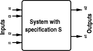
 .
.