| Submission Procedure |
A Novel Type of Skeleton for Polygons
Franz Aurenhammer Institute for Theoretical Computer Science, Graz University of Technology, Klosterwiesgasse 32/2, A-8010 Graz,Austria {oaich,auren}@igi.tu-graz.ac.at Bernd Gärtner Institut für Informatik Freie Universität Berlin Takustraße 9, D-14195 Berlin, Germany {alberts,gaertner}@inf.fu-berlin.de Abstract: A new internal structure for simple polygons, the straight skeleton, is introduced and discussed. It is composed of pieces of angular bisectores which partition the interior of a given n-gon P in a tree-like fashion into n monotone polygons. Its straight-line structure and its lower combinatorial complexity may make the straight skeleton preferable to the widely used medial axis of a polygon. As a seemingly unrelated application, the straight skeleton provides a canonical way of constructing a polygonal roof above a general layout of ground walls. Keywords: Simple polygon, angular bisectors, internal skeleton, roof construction 1 Introduction and Basic Properties
The purpose of this paper is to introduce and discuss a new and interesting internal structure for simple polygons in the plane. The new structure, called the straight skeleton, is solely made up of straight line segments which are pieces of angular bisectors of polygon edges. It uniquely partitions the interior of a given n-gon P into n monotone polygons, one for each edge of P. The straight skeleton, in general, differs from the well-known
medial axis of P which consists of all interior points
whose closest point on P's boundary is not unique;
see e.g. Lee [L]. If P is convex
then both structures are identical. Otherwise,
the medial axis contains parabolically curved segments in the neighborhood
of reflex vertices of P which are avoided by the straight skeleton.
If P is rectilinear then the straight skeleton is the medial axis
of P for the While the medial axis is a Voronoi-diagram-like concept, the straight skeleton is not defined using a distance function but rather by an appropriate shrinking process for P. Imagine that the boundary of P is contracted towards P's interior, in a self-parallel manner and at the same speed for all edges. Lengths of edges might decrease or increase in this process. Each vertex of P moves along the angular bisector of its incident edges. This situation continues as long as the Page 752 boundary does not change topologically. There are two possible types of changes:
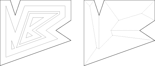
After either type of event, we are left with a new, or two new, polygons which are shrunk recursively if they have non-zero area. Note that certain events will occur simultaneously even if P is in general position, namely three edge events letting a triangle collapse to a point. The shrinking process gives a hierarchy of nested polygons; see Figure 1(a). The straight skeleton, S(P), is defined as the union of the pieces of angular bisectors traced out by polygon vertices during the shrinking process. S(P) is a unique structure defining a polygonal partition of P. Each edge e of P sweeps out a certain area which we call the face of e. Bisector pieces are called arcs, and their endpoints which are not vertices of P are called nodes, of S(P). See Figure 1(b).
As far as it is known to the authors, no attention has been paid to the straight skeleton in the literature. We show that S(P) has several useful properties. For example, its tree structure implies that, if P is non-convex, S(P) is of smaller combinatorial size than the medial axis of P. The latter, though also being a tree, has to distinguish between curved and straight parts of arcs. To be precise, if P is an n-gon with r reflex vertices then S(P) realizes 2n-3 arcs whereas the medial axis of P realizes 2n+r-3 arcs, r of which are parabolically curved. As a particularly nice property, S(P) partitions P into monotone polygons. A three-dimensional interpretation of S(P), the roof model, is discussed in Page 753 Section 2 and Section 3. This leads us to the interesting and practically relevant question of constructing a roof of fixed slope above a given layout P of ground walls. The roof model allows us to gain more insight into the structure of straight skeletons and, in particular, gives a way to define S(P) non-procedurally. On the other hand, S(P) provides a canonical way of constructing a roof above P. We show that the roof corresponding to S(P) exclusively has the property that rainwater runs off from each roof facet to its defining edge of P. We also disprove the obvious conjecture that roofs can be expressed as lower envelopes of simply-shaped linear functions. Hence S(P) is no Voronoi-diagram-like structure, a fact that complicates its algorithmic construction. Section 4 offers a short discussion of the presented topic. The rest of this section describes some basic properties of S(P). Lemma 1. S(P) is a tree and consists of exactly n connected faces, n-2 nodes and 2n-3 arcs. Proof. The construction of a face f(e) starts at its edge, e, of
P. f(e) cannot be split even if e happens to be. The construction of
f(e) is completed when (every part of) e has shrunk to zero. As e
cannot reappear again, f(e) is connected, and S(P) is acyclic. That
is, S(P) is a tree with the n vertices of P as leaves, and has n-2
nodes and 2n-3 arcs. Two types of arcs of S(P) can be distinguished. Each arc is a piece of the
angular bisector of two edges e and e' of P or, more precisely, of the
lines l(e) and l(e') supporting these edges. Note that the angular
bisector of l(e) and l(e') actually consists of two lines that
intersect
at Each convex (reflex) vertex of P obviously gives rise to a convex (reflex) arc of S(P). While convex arcs can also connect two nodes of S(P), this is impossible for reflex arcs. Lemma 2. Reflex arcs of S(P) only emanate from reflex vertices of P. Proof. Let vu be an arc emanating from some vertex v of P. Then u is a node which corresponds either to an edge event or to a split event. It suffices to show that, after the event, S(P) continues at u with convex arcs only. In the former case, let vw be the vanishing edge. Since the arc wu meets vu at u, u is a convex vertex of the shrunk polygon at the moment the event takes place. In the latter case, the polygon splits at u. It is obvious that, at that moment, u is a convex vertex of both new polygons. In conclusion, each new vertex generated during the
shrinking process is convex. Hence the arcs continuing
at u are convex, too. Page 754 2 Graph Model and Roof Model
It seems hard to give a non-procedural definition of the straight skeleton,
as it is available for the medial axis using distances from the boundary.
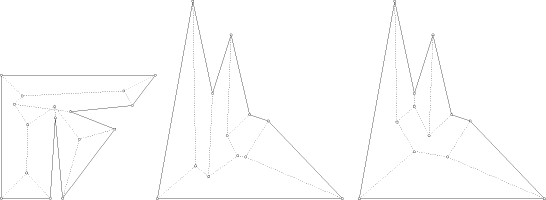
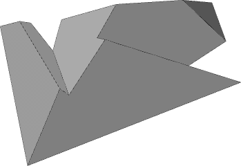
The shrinking model suggests to define the distance of a point S(P) can be seen as a geometric graph whose arcs are pieces of bisectors defined by the edges of P, each arc being labeled by an ordered pair of edges. Arcs are bounded by P's vertices, which have degree 1 in the graph, and by S(P)'s nodes which have degree 3. Each node is the intersection point of three bisectors. (To ease the discussion, we exclude degeneracies caused by special shapes of P.) Its three incident arcs have labels of the form (a,b), (b,c), (c,a), and the ordering of each label (a,b) indicates the position of the faces f(a) and f(b) relative to the arc. We call a graph with these properties a bisector graph for P. However, these properties are by far to weak to imply uniqueness. A bisector graph need not even define a partition of P (and thus a face structure) as long as we do not require it to be plane. Restriction to plane graphs, even to plane trees (as it is the case for S(P), see Lemma 1) still gives no unique structure; see Figure 2. Alternatively, and more intuitively appealing, a plane bisector graph for P can be viewed as the projection of a three-dimensional object. Let P be contained in the horizontal plane Page 755 We now define a roof for P as a terrain (graph of a piecewise-linear
continuous function) over P whose facets are from
the halfplanes above and whose intersection
with
Theorem 3. Every roof for P corresponds to a unique plane bisector graph for P, and vice versa. Proof. Let R be a roof for P. By the choice of the halfplanes supporting R's facets, the edges of R project vertically to pieces of edge bisectors. Bisectors are labeled correctly, as each node of the resulting graph is the projected intersection of three halfplanes. Finally, the graph is plane as R is a terrain. Let G be a plane bisector graph for P. Each node u of G is the center
of a circle that touches three lines supporting the three edges of P
that define u. We lift up u vertically by
the radius of this circle, getting a point In the unique roof of a plane bisector graph, convex arcs
of the graph give rise to
ridges of the roof
(both facets going downwards) and reflex arcs give rise
to valleys (both facets going upwards). Note the impossibility of
having one facet upwards and the other downwards, as all
facets have the same slope.
Endpoints of ridges or of valleys that are not polygon vertices
are called corners of the roof. They lie above plane
Page 756 It is interesting -- also from a practical point of view -- to study which kind
of roofs are legitimate by our definition. Surprisingly, a halfplane may
contribute more than one facet to the roof.
That is, an edge of P may yield several faces in the bisector graph.
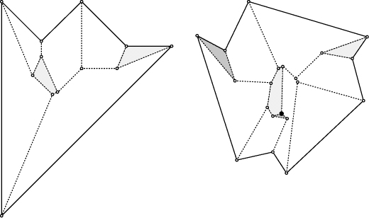
Even local minima may arise; see Figure 4. The first anomaly
indicates that, in contrast to the straight skeleton, the size
of general plane bisector graphs need not be linear.
A trivial upper bound is Despite of the ambiguity of plane bisector graphs, their faces have a nice property which is easy to prove using the roof model. Lemma 4. Each face f(e) of a plane bisector graph is monotone in direction of its defining edge e. That is, the intersection of f(e) with every line normal to e is connected. Proof. Let F be the roof facet corresponding to f(e). Recall Page 757 3 Islands
The concept of straight skeleton
S(P) offers a unique way of constructing
a roof avoiding the anomalies mentioned above,
for a general layout P of ground walls.
When viewing S(P) as a roof, the shrinking process defining S(P)
has a nice physical interpretation. The roof is interpreted as
an island with P deliminating the coast. Water level stands at
plane This flooding process gives sense for non-island roofs, too. In fact, each roof for P defines a particular flooding process which is uniquely determined by a sequence of events sorted by increasing height. This fact will allow us to characterize I(P) among all possible roofs for P. Let R be an arbitrary roof for P. In the flooding process for R, we now may encounter new types of events beside edge events and split events. For example, it is possible that the water level reaches a local minimum of a facet at a corner c of R. If c is no local minimum of R then -- in the shrunk polygon -- an edge parallel to some edge of P starts expanding there (inverse edge event). Else a triangular hole appears (three simultaneous inverse edge events). Compare Figure 4. This list of events is not complete. Lemma 5. If R is a roof for P different from I(P) then R has a valley not incident to a (reflex) vertex of P. That is, R contains a valley that connects two corners of R. Proof. Note first that the flooding process starts in the same way
for all possible roofs for P. That is, P starts to shrink
in a unique manner. Now consider the first event that makes R
differ from I(P). This event must come from a corner of R.
If it would come from a corner of I(P) then an edge event or a split
event would miss in the flooding process for R, contradicting
its terrain property.
Let now c be the corner of R that corresponds to this event.
Immediately before reaching c, water surrounds the part of R
containing c and defines a shrunk polygon P' whose boundary
deliminates the local coast. Obviously, the part of I(P) above P'
is I(P'). As I(P') continues with the next-higher edge event or
split event, and c is no corner of I(P'), c corresponds to
a non-island type of event. In particular,
some edge that does not appear in P' must be involved
in this event. That is, some new edge(s) start(s) expanding.
An expansion of edges, however, can only take place at reflex arcs.
Hence some valley of R starts at c, and the lemma
is proved. Theorem 6. Let R be a roof for P. Then R=I(P) if and only if each valley of R is incident to P. Proof. Combine Lemma 2 and Lemma 5. It is easy to see that each roof for P has the same surface area. A natural question to ask is whether I(P) optimizes some other parameter among all possible roofs for P. However, I(P) achieves neither the maximum nor the minimum roof volume in general; see Figure 2 (shows I(P) in the middle) and Figure 5, Page 758 respectively. These examples also reveal that neither the maximum nor the minimum global roof height is guaranteed. Still, the facets of I(P) obey a nice rule which is particular to I(P). Let R be any roof for P. For a point x on R, let
g(x) denote the path that starts from x and
follows the steepest gradient on R. We say that a facet F
of R has the gradient property if, for every Theorem 7. A roof R for P is the island of P if and only if each facet of R fulfills the gradient property. Proof. Assume R=I(P). Let e be an edge of P, let F be its
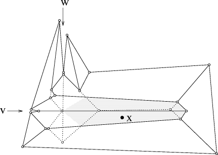
facet in R, and consider a point Now assume A physical interpretation of Theorem 7 is that on I(P), and only there, every raindrop that hits a facet F runs off to the edge defining F. Theorem 6 and Theorem 7 can be used as definitions for I(P) and thus for S(P). It would be elegant, however, to have a definition which does not resort to the explicite structure of I(P). One approach that suggests itself is to try to express I(P) as the lower envelope of partial linear functions, each function being defined locally by an edge of P and its appropriate neighborhood. However, the example in Figure 5 shows us that such functions do not exist. Consider the reflex vertex v, and let e be the edge incident to
v whose facet in R(P) contains the point x.
Let This undesirable property of I(P) reveals that S(P) is no Voronoi-diagram-like structure. To be more precise, S(P) cannot be interpreted as some Voronoi diagram for the edges of P, if the underlying distance function is defined without prior knowledge of S(P). 4 Discussion
The contributions of this paper are two-fold: The introduction of a new internal structure for simple polygons, and the first systematic treatment of the problem of constructing a roof above a polygonal layout of ground walls. Page 759 The general advantages of the straight skeleton over the medial axis are its straight-line structure and its lower combinatorial complexity. Both structures reflect the shape of a polygon in a compact manner. However, the straight skeleton is more sensible to changes of the shape. Adding a reflex vertex with very small exterior angle may alter the skeleton structure completly. If this effect is undesirable then such vertices may be cut locally, without much changing the polygon and achieving exterior angles of at least 90 degrees. The straight skeleton provides a unique way of computing a polygonal roof, given a general placement of ground walls. We have shown that roofs are highly ambiguous objects, and that constructing a roof is a non-trivial task. To our knowledge, the roof construction method presented here is the first one in the literature. A disadvantage of straight skeletons is the lack of a Voronoi diagram structure, which excludes the well-developed machinery of constructing Voronoi diagrams [A] from application, and makes tailor-made algorithms neccessary. Powerful techniques like divide-and-conquer or incremental insertion can be shown to fail. The most promising approach,
which might work sufficiently well in practical situations,
is a simulation of the polygon shrinking process.
The trivial method would consider
each pair of edges of the current polygon(s) to detect the next
edge event or split event. As each event corresponds to
a node of S(P), this leads to an Of course, the determination of the next edge event is easy as it can be done Page 760 locally, but finding the next split event in low worst-case time is by no means trivial. A heuristic that can be expected to be fast on the average is tracing the reflex vertices through a suitable partition of the shrinking polygon. This would lead to an O(n) space algorithm whose running time depends (more or less) on the number of reflex vertices. The challange is to find an algorithm with performance comparable to medial axis algorithms; for example, O(n log n) time. We do not further persue this matter here. Acknowledgements: The second author would like to express thanks to G.L. Sicherman from AT&T Bell Labs. for drawing his attention to straight skeletons. Discussions on the presented topic with J.-D. Boissonnat, O. Devillers, M. Formann, R. Klein, D.T. Lee, G. Rote, and K. Varadarajan are gratefully acknowledged. Thanks also go to Th. Natschläger for implementing an algorithm for visualizing islands. References
[A] F. Aurenhammer, Voronoi diagrams -- a survey of a fundamental geometric data structure, ACM Computing Surveys 23, 3 (1991), 345 - 405. [L] D.T. Lee, Medial axis transformation of a planar shape, IEEE Trans. Pattern Analysis and Machine Intelligence, PAMI-4 (1982), 363-369. [K] D.G. Kirkpatrick, Efficient computation of continuous skeletons, Proc. 20th Ann. IEEE Symp. FOCS (1979), 18 - 27.
Page 761
|
|||||||||||||||||
 -metric. Skeletons have numerous applications
inside and outside computer science as is documented e.g. in
Kirkpatrick [

 . We single out the one relevant for S(P) as
follows.
Each line l(e) defines a halfplane h(e) that contains P near e.
One of the bisector lines intersects the wedge
  while the other
avoids it. We call the former the bisector of the edges e and e'
and will ignore the latter in our considerations.
An arc a defined by this bisector is called a convex
arc or a reflex arc depending on whether its wedge contains e
and e' in its boundary or not. We also consider a
as labeled by the ordered pair (e, e').
The order reflects the side of a where l(e) contributes to the boundary
of the wedge.
 from an edge e as the normal distance from x to the supporting
line l(e). This definition fails as e might have vanished before
l(e) sweeps across x.
Below we discuss two other approaches, the graph model and the roof model,
that allow us to gain more insight into the structure of straight skeletons.
 , and
associate each edge e of P with a halfplane
  in three-space.
 is bounded by l(e),
has a fixed slope (say 45 degrees) with respect to
  ,
and is inclined towards P. For any two distinct edges e and e' of P,
the halfline
  projects vertically to the
(relevant halfline of the) bisector of
e and e'.
  is the boundary of P.
Intuitively speaking, this is a 45-degree roof with P's edges
as ground walls; see Figure 3.
 in three-space.
Note that, if u's arcs are labeled (a,b), (b,c), (c,a), then
  .
Let now f be a face of G. Each arc bounding f has a label
of the form (x,e), where e is a fixed edge of P,
and x runs through the edges defining the faces
of G adjacent to f. Hence
  for all
nodes u of f. Clearly, e
  by definition.
(Note, however, that e does not necessarily bound f.)
This shows that f is lifted up by to a planar facet.
As G is a plane graph, we obtain a piecewise-linear function over P.
This function is continuous as facets stemming from faces f(e) and
f(e') touch along the lifted arc with label (e,e').
 and project to the nodes of the graph.
 , as each node
of the graph comes from a different triple of edges of P.
The second anomaly is particularly
undesirable for real-world roofs as rain water cannot run off.
 and consider some line L in
  normal to e.
Obviously, L has slope 1, which is the maximum possible on
the roof. Assume now that f(e) is not monotone
in direction e. Then L can be chosen so as to leave F at some point x
and to re-enter F at some higher point y. In between, the roof
consists of facets contained in halfplanes different from
  .
Hence, when following the vertical projection of the segment xy on the roof,
one traces segments of slope less than 1, thus
ending up at a point vertically below y. This implies that the roof is not
continuous -- a contradiction.
 and rises steadily during the shrinking process.
Splits occur when the water surrounds local maxima of the island.
The unique roof for P corresponding to S(P) will be
called the island of P, I(P), in the sequel.
 ,
g(x) reaches the edge e defining F either in its interior or at a vertex.
 then we are done. Else y lies in a valley V of
R. This is because valleys correspond to reflex arcs of the bisector
graph, and only these arcs form an angle larger than 90 degree with
e. It remains to be observed that g(x) follows V to its lowest point
which, by
  . By Lemma 5, R contains a valley
V whose lowest point is a corner c of R.
Let F be a facet of R which has c as a local minimum, and let
e be its defining edge. Then we can choose a point
  near V
such that g(x) reaches and follows V and ends at
  .
. be the graph of some
partial linear function for e.
The facet of e in I(P) does not contain x, as I(P) is above
  at x. So, if I(P) is the lower envelope of
the functions
  , then
  must not contain x.
On the other hand, a change of P not in the neighborhood of e,
namely moving the reflex vertex w slightly upwards,
makes R(P) the valid island of P. Now
  has to contain
x in order to ensure the envelope property for the modified
polygon. This shows that
  cannot be defined without
knowledge of I(P).
 time and O(n)
space algorithm. Organizing the events in a priority
queue brings down the construction time to
  ,
but at an expense of
  storage.