| Submission Procedure |
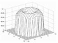
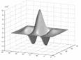
Ridge Orientation Estimation and Verification Algorithm for Fingerprint EnhancementLimin Liu Tian-Shyr Dai Abstract: Fingerprint image enhancement is a common and critical step in fingerprint recognition systems. To enhance the images, most of the existing enhancement algorithms use filtering techniques that can be categorized into isotropic and anisotropic according to the filter kernel. Isotropic filtering can properly preserve features on the input images but can hardly improve the quality of the images. On the other hand, anisotropic filtering can effectively remove noise from the image but only when a reliable orientation is provided. In this paper, we propose a ridge orientation estimation and verification algorithm which can not only generate an orientation of ridge flows, but also verify its reliability. Experimental results show that, on average, over 51 percent of an image in the NIST-4 database has reliable orientations. Based on this algorithm, a hybrid fingerprint enhancement algorithm is developed which applies isotropic filtering on regions without reliable orientations and anisotropic filtering on regions with reliable orientations. Experimental results show the proposed algorithm can combine advantages of both isotropic and anisotropic filtering techniques and generally improve the quality of fingerprint images. Keywords: Fingerprint, enhancement, Gabor filter, orientation estimation Categories: I.4.3, I.4.9, I.5.4 1 IntroductionIt is obvious that fingerprints are the most widely applied biometric identifier. With the help of high performance computers, Automatic Fingerprint Identification Systems (AFIS) have gradually replaced human experts in fingerprint recognition as well as classification. However, fingerprint images contain noise caused by factors such as dirt, grease, moisture, and poor quality of input devices and are one of the noisiest image types, according to O'Gorman [O'Gorman 1998]. Therefore, fingerprint enhancement has become a necessary and common step after image acquisition and before feature extraction in the AFIS. A fingerprint consists of two special direction-oriented parts: ridges and valleys, where valleys are the space between ridges and vice versa. These directional patterns contain various fingerprint features including a small number of singular points (delta and core point) and randomly distributed local discontinuities called minutiae (see Fig. 1). Page 1426 Enhancement process should not only increase the contrast between the ridges and valleys [O'Gorman 1989] but also retain these fingerprint features, since they are crucial for the later recognition process. Furthermore, enhancement should not create spurious structures because that will create false singular points and minutiae. Figure 1: Fingerprint features: core point (in circle), delta point (in triangle), minutiae-ridge ending (in square), and minutiae-ridge bifurcation (in diamond). Matched filtering is a widely used image-processing operation in reducing image noise. Generally speaking, filtering techniques can be categorized as isotropic and anisotropic based on whether the filter kernel is orientation sensitive. The two most commonly used isotropic filters are the median filter [Lee 1985] and Gaussian filter [Shapiro 2001]. Almansa and Lindeberg proposed a specially tailored isotropic diffusion scheme with an isotropic filter [Almansa 2000]. Wang proposed a bandpass filter (see Fig 2(a)) to enhance regions containing singular points [Wang 2004]. Isotropic filtering can properly preserve features on the input images but can hardly improve the quality of the image. On the other hand, anisotropic filtering can effectively remove noise from the image but only on the condition that a reliable orientation is provided. Hong et al. used Gabor filter banks to enhance fingerprint images and reported good performance [Hong 1998]. Gabor filters (see Fig. 2(b)) have both orientation and frequency-selective properties. Over the years, a number of researchers have applied Gabor filters to enhance flow-like patterns [Jain 1997, Maio 1997, Hong 1998, Yang 2003]. Yang proposed an improved version called modified Gabor filter which can reduce the False Rejection Rate by approximately 2% at a False Acceptance Rate of 0.01% [Yang 2003].
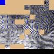
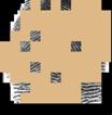
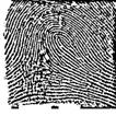
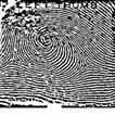
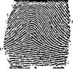
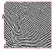
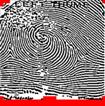
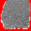
Figure 2: (a) A bandpass filter (from [Wang 2004]), and (b) an even symmetric Gabor filter (from [Jain 1997]). Page 1427 If we can guarantee the orientation is reliable, then anisotropic filtering can produce better results than isotropic filtering, since the ridge flows are direction-oriented by nature. However, if the orientation is not correct, for instance, orthogonal to ridge flows, than the anisotropic filtering will corrupt the real ridge patterns and consequently generate false fingerprint features. Generally speaking, a fingerprint orientation estimation algorithm can derive acceptable ridge orientation when the quality of the image region is relatively good. To differentiate high quality regions from low quality regions, Hong et al. modelled the ridge and valley pattern as a sinusoidal wave and computed frequency and variance to determine the quality of fingerprint images [Hong 1998]. An image was divided into recoverable and unrecoverable regions, and the fingerprint enhancement was performed only on recoverable regions. Furthermore, fingerprints with over 60% unrecoverable regions were rejected. Yao et al. calculated the mean and variance of a sub-block of images to determine the quality [Yao 2002]. However, neither was able to distinctly differentiate good regions from bad regions [Lee 2006]. Ratha and Bolle proposed a method for image quality estimation in the wavelet domain which is unsuitable for uncompressed images [Ratha 1999]. Lee et al. proposed a model-based quality estimation of fingerprint images based on gradient operator with 8x8 blocks in which the global features are ignored and the quality of images is defined by whether minutiae can be detected [Lee 2006]. Park and Kwon proposed a quality measurement approach based on 8 directional slots chain codes of sliced block, but this approach requires human experts and there are some cases in which a poor quality block was marked as good quality and vice versa [Park 2003]. Lim et al. observed global uniformity and local texture patterns in fingerprint images, and this approach requires determining the weights for global and local quality measurements [Lim 2002]. There are many methods for ridge orientation estimation in the literature, and most of them are based on gray-scale relationship between pixels. Methre et al. computed gray consistency along 16 directions at each pixel and the orientation of the best consistency is taken as the ridge orientation [Methre 1987]. Hung divided pixels into ridge and non-ridge pixels and estimated ridge orientation by computing the consistency of pixel type [Hung 1993]. Nagaty [Nagaty 2003] and Zhu et al. [Zhu 2006] evaluated the correctness of ridge orientation based on neural network. The correctness of these methods depends highly on the data used in the learning phase. The most popular method for ridge orientation estimation is the gradient-based method [Maio 1997, Hong 1998, Bazen 2002, Yang 2003, Cheng 2004]. It calculates the gradient vector of each pixel, and, ideally, the gradient vector direction of an edge pixel would be orthogonal to the ridge orientation. However, if the dominate gradient of edge pixels is not orthogonal to the ridge orientation, a falsely estimated orientation will result. In other words, all of these methods cannot guarantee the correctness of the estimated ridge orientation. In this paper, we propose a ridge orientation estimation and verification algorithm that can not only generate an orientation of ridge flows but also verify its reliability. If the orientation is not reliable, then the orientation of the region will be marked with a specific flag. More precisely, the verified orientations are guaranteed to be reliable. Furthermore, the limited number of grey levels, in most cases 256, can hardly represent the ideal sinusoidal wave used to model fingerprint ridge and valley. This is because fingerprint images contain noise, and the width of a ridge can be as small as a few pixels. Page 1428 Hence, the proposed algorithm uses K-slope method to calculate the sinusoidal wave curvature [Rosenfeld 1982]. K-slop method can properly reduce the effect from noise pixels during the calculation of the ridge curvature. Since the proposed algorithm is able to verify orientation reliability, we also propose a hybrid fingerprint enhancement algorithm which applies anisotropic filtering on regions with reliable orientations and isotropic filtering on regions without reliable orientations. The rest of the paper is organized as follows. Section 2 reviews the isotropic and anisotropic filtering techniques with examples and illustrates the advantages and disadvantages of both techniques. Section 3 describes the proposed ridge orientation estimation and verification algorithm followed by the proposed hybrid enhancement algorithm with experiments in Section 4. We then conclude our work in Section 5. 2 Isotropic and Anisotropic FilteringTo illustrate the isotropic and anisotropic filtering, three fingerprint images are selected from the NIST-4 database [Watson 1992] as shown in the top row of Fig. 3 where (a) has a grid pattern on the bottom-left of the image, (b) has a large smudged region on the top-left of the image, and (c) shows a relatively clean image (high contrast). The results of applying two isotropic filtering methods on these three images are shown in the lower two rows of Fig. 3 where the middle row shows the results of the bandpass approach proposed in [Wang 2004] and the bottom row shows the results of the median filter with adaptive thresholding proposed in [Huang 1998, Ailisto 2003].
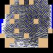
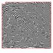
Figure 3: Top row: examples of fingerprints from NIST-4. Middle row: enhanced results by bandpass filtering. Bottom row: enhanced results by median filtering. Page 1429 It is observed that the results of these two isotropic filtering can properly preserve the features of the input images as well as the noise such as the words "LEFT THUMB" as shown in the middle column of Fig. 3. Fig. 4 shows the enhanced results after applying the anisotropic Gabor filtering on the same examples with different sizes of Gabor blocks: 9×9, 15×15, and 23×23 pixels, respectively. Each Gabor block will be assigned with an orientation calculated by a certain procedure which will be discussed in the next section. Fig. 4(c) shows that a good quality image will retain most of its fingerprint features when divided by blocks of different sizes, and that the smaller the block size, the higher the enhanced quality. Furthermore, the words "LEFT THUMB" are properly removed as shown in the middle column of Fig. 4. However, in the bottom-left region of the top image of Fig. 4(a) and the top-left region of the top image of Fig. 4(b), spurious structures corrupt the continuity of ridge flows and create many false features due to incorrectly estimated orientations. Since no verification mechanism has been introduced, we can only hope the orientation produced by the specific orientation estimation method is reliable. Therefore, when using algorithms that adopt anisotropic filtering technique, we can never be sure whether the enhanced results contain false features or not. Such noisy regions may be properly enhanced while enlarging the block size as shown in the bottom row of Fig. 4(a) and (b). This is because in these cases, enlarging the Gabor block can derive an orientation closer to the real flow orientation. Unfortunately, a large block size has a serious side effect?destroying the ridge details. For instance, the left delta point in the bottom image of Fig. 4(b) is destroyed, and so is the center core point in the lower image of Fig. 4(a).
Figure 4: Enhanced results of Fig. 3 by Gabor filters with different block sizes: 9x9, 15x15, and 23x23 pixels, respectively (top to bottom). Page 1430 Many researchers apply a relatively small block and smooth the orientation by Gaussian function. For example, Hong filtered the orientation field using a low-pass Gaussian filter [Hong 1998]. However, this approach failed when a noisy region is too large as shown in Fig. 2(a) and (b). Furthermore, the orientation of a noisy block or singular point block will affect the orientation of its neighbours during the smoothing process. 3 Orientation Estimation and VerificationAs aforementioned, many methods of orientation estimation have been proposed, and the simplest and most frequently adopted method is the gradient-based approach [Hong 1998, Bazen 2002, Yang 2003, Cheng 2004, Lee 2006]. To illustrate the result of gradient-based approach, six relatively clean ridge patterns (high contrast) are shown on the top row of Fig. 5 where (a) and (b) contain minutiae (ridge bifurcation and ridge ending), (c) and (d) contain singular points (delta and core point), and the other two are noisy regions. Fig. 5(e) shows a circle-like pattern with a white circle having a black dot inside, and (f) looks like a grid pattern with orthogonal ridge flows overlapping. Figure 5: Six ridge patterns and their orientations calculated by Kirsch, Robinson, Sobel, and Prewitt operators. The associated orientations calculated by the gradient-based approach with different operators (Kirsch, Robinson, Sobel, and Prewitt [Shapiro 2001]) are also shown in Fig. 5. It can be observed that these four gradient operators generate relatively consistent block orientations. However, only the orientations of patterns (a) and (b) are reliable, and those of the other four are not. Actually, patterns (c) to (f) should not be assigned any orientation since no orientation can properly represent the directions of ridge flows in these blocks. Ideally, the intensity value of the orientation orthogonal to ridge flows can be modelled as a sinusoidal plane wave (see Fig. 6(a)). The width of the sinusoidal frequency can be considered as the ridge frequency. This ridge frequency calculation function works under an assumption that a reliable ridge orientation is already given. However, the previously-mentioned algorithms will generate a ridge orientation no matter how the image quality is. A noisy region may lead to a wrong ridge orientation and a wrong ridge frequency. Page 1431 In such a case, applying an anisotropic filter on this noisy region can hardly improve the quality of the image but introduce more false ridges and features instead. More precisely, if we cannot guarantee the ridge orientation is correct, then we should not apply the anisotropic filtering technique.
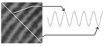
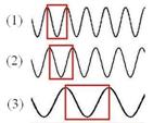
Figure 6: (a) A fingerprint ridge flows with ideal corresponding histogram. (b) Six directions for histograms examination. A good orientation estimation algorithm should not only calculate correct flow orientation, but also prevent assigning an orientation to noisy blocks or blocks containing singular points. To achieve this goal, we propose an orientation estimation algorithm with verification mechanism. If we observe the intensity histograms of the ridge flows shown in Fig. 6(a) in six different directions as shown in Fig. 6(b), we can derive six histograms for these directions (see Fig. 7). From these histograms, we can calculate the associated ridge lengths as shown in the boxes in Fig. 7, which monotonically increase from directions (1) to (4) and monotonically decrease from directions (4) to (6) (and eventually to (1)). Note that the ridge length in Fig. 7(4) is defined as infinite because the histogram does not contain a complete wave cycle. More precisely, the ridge length is infinite while the histogram direction is parallel to the ridge flow. On the other hand, the ridge length has a minimum value while the histogram direction is orthogonal to the ridge flow.
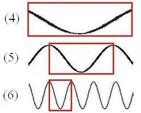
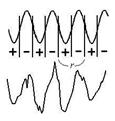
Figure 7: The histograms of the six directions shown in Fig. 6(b). The curvature value of an ideal sinusoidal plane wave should have a repeating increase-decrease pattern as shown on top of Fig. 8(a). The ridge length, r, then can be defined as the sum of the curvature increase length and the curvature decrease length. However, real fingerprints contain a lot of noise and therefore a real histogram may look like the wave shown on the bottom of Fig. 8(a). To prevent noise from influencing the process of ridge length calculation, we use the K-slope method to calculate the wave curvature [Rosenfeld 1982]. Page 1432 Fig. 8(b) shows the relationship between histogram direction and ridge length of the image shown in Fig. 6(a) where x-axis represents the histogram direction and y-axis represents the ridge length. In this example, θ is 135 degrees, since ridge length has a minimum value under such a direction and the same conclusion can be made when the direction angle is 180-θ (-45 degrees) or θ+180 (+315 degrees).
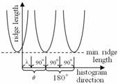
Figure 8: (a) Ideal and real fingerprint histogram. (b) Relationship between ridge length and histogram direction. Fig. 8(b) indicates several important rules that include (1) the unique minimum ridge length shall be reached within 180 degrees, (2) the unique maximum ridge length (infinite) shall be reached within ±90 degrees from the direction with minimum ridge length, (3) the relationship between ridge length and histogram direction repeats every 180 degrees, (4) the ridge lengths from minimum ridge length direction θ to θ+90 monotonically increase, and (5) the ridge lengths from maximum ridge length direction λ to λ+90 monotonically decrease. Apparently, a noisy ridge region can not follow all of these rules. We therefore propose a ridge orientation estimation and verification algorithm based on these rules. The proposed algorithm can be outlined as follows,
These rules can be easily violated due to the presence of minutiae, singular points, or noise. But on the other hand, it also means the orientation of a certain block must be reliable. The six examples shown in Fig. 5 will all be marked as uncertain by this orientation estimation algorithm, due to minutiae in Fig. 5(a) and (b), singular points in (c) and (d), and noise in the other two. Page 1433 Although the proposed orientation estimation and verification algorithm failed to assign orientations to Fig. 5(a) and (b), it successfully marks Fig. 5(c) to (f) as uncertain instead of assigning approximate orientations and hoping they are correct. 4 Enhancement Algorithm and ExperimentsA good fingerprint enhancement algorithm should generally improve the quality of an image rather than work on some specific images or specific regions of an image. To achieve this goal, we propose a hybrid enhancement algorithm combining isotropic and anisotropic filtering techniques. The enhancement algorithm can be outlined as follows,
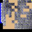
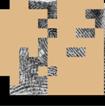
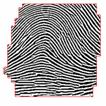
When the orientation estimation and verification algorithm is applied on the 4,000 images in the NIST-4 database, approximately 48 percent of the foreground image on average is marked as uncertain when the block size is 23x23. The performance of our enhancement algorithm depends on the particular isotropic and anisotropic filters applied on certain and uncertain blocks. In our experiments, we used Gabor filer and median filter with adaptive thresholding. After applying the ridge orientation estimation and verification algorithm to the images shown in Fig. 3, certain blocks were assigned with proper orientations as shown on the top row of Fig. 9, and the bottom row shows the uncertain blocks.
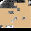
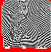
Figure 9: Top row: certain blocks and bottom row: uncertain blocks. Page 1434 Fig. 10 shows the enhanced result of Fig. 3 in bandpass filtering (top row), Gabor filtering (middle row), and our proposed hybrid enhancement algorithm (bottom row). If we compare the bottom row with the top and middle rows in Fig. 10, we can see that a lot of noise that appear in the top rows of Fig. 10 no longer exist in the bottom row, and that the singular points are closer to the real ridge patterns in the bottom row than in the middle row. Even though the enhanced results of the proposed algorithm still contain noise, the hybrid algorithm will not create false singular points as shown in the middle row of Fig. 10 (a) and (b). It is clear that the hybrid algorithm outperforms single isotropic or anisotropic filtering techniques. Furthermore, for a high quality fingerprint such as Fig. 3(c), the proposed hybrid enhancement algorithm will remove noise without corrupting the ridge flow patterns as shown in Fig. 10(c).
Figure 10: Enhanced results of Fig. 3. Top row: enhanced by bandpass filtering. Middle row: enhanced by Gabor filters (15x15). Bottom row: enhanced by the proposed hybrid algorithm. 5 ConclusionsFingerprint enhancement is a common and critical step in modern AFIS that can greatly reduce computation time. The enhancement process should not only increase the contrast between ridge and valley, but also properly remove noise in the images. Furthermore, a good enhancement algorithm should generally improve the quality of all images instead of improving only portions of the input images (or a portion of an image) and creating spurious fingerprint features on the rest. Page 1435 The matched filtering technique, a general image-processing operation, is widely used for the purpose of removing noise and has been adopted by many researchers on fingerprint image enhancement. The kernel of filters can be grouped into two types: isotropic and anisotropic filter. Isotropic filtering can properly preserve features on the input images but can hardly improve the quality of the images. On the other hand, anisotropic filtering can effectively enhance fingerprint images but only when a reliable orientation is provided. Since no verification mechanism has been introduced, we can only hope the orientation produced by the specific orientation estimation method is reliable. In this paper, we propose a ridge orientation estimation and verification algorithm which marks non-flow shaped regions with a special flag rather than assigns an orientation. Verified orientations are guaranteed to be reliable. Then, a hybrid fingerprint enhancement algorithm is proposed by adopting anisotropic filtering on regions with reliable orientations and isotropic filtering on the rest of the image. With the ability to determine whether the orientation of a region is reliable or not, the proposed hybrid enhancement algorithm can combine advantages of both isotropic and anisotropic filtering techniques to improve the quality of all kinds of fingerprint images. 6 Future WorkFor future work we would like to utilize the reliable orientation to restore the orientation of blocks without a verified orientation to reduce the ratio of uncertain region in fingerprints. For example, the orientation of a block without a verified orientation surrounded by eight blocks with verified orientations can be assigned with the average of its neighbours orientations if these orientations are consistent (smaller than a threshold). However, the orientation restoration process requires further study which is beyond the scope of the current research. Acknowledgements The authors would like to thank Mr. Yen-Chun Liu for his programming work to prepare many of the fingerprint images and orientation data. References[Ailisto 2003] H. Ailisto, M. Lindholm, and P. Tikkanen. A Review of Fingerprint Image Enhancement Methods. Int. J. Image Graphics, 3(3):401-424, 2003. [Almansa 2000] A. Almansa and T. Lindeberg. Fingerprint enhancement by shape adaptation of scale-space operators with automatic scale selection. IEEE Trans. on Image Processing, 9(12): 2027-2042, 2000. [Bazen 2002] A. M. Bazen and S. H. Gerez. Systematic methods for the computation of the directional fields and singular points of fingerprints. IEEE Trans. on Pattern Anal. Mach. Intell., 24(7):905-919, 2002. [Cheng 2004] J. Cheng and J. Tian. Fingerprint enhancement with dyadic scale-space. Pattern Recognition Letters, 25(11):1273-1284, 2004. Page 1436 [Hong 1998] L. Hong, Y. Wan, and A. K. Jain. Fingerprint image enhancement: algorithm and performance evaluation. IEEE Trans. on Pattern Anal. Mach. Intell., 20(8):777-789, 1998. [Huang 1998] C. Y. Huang, FLAG: The fault-line analytic graph and fingerprint classification, unpublished doctoral dissertation, New Jersey Institute of Technology, 1998. [Hung 1993] D. Hung. Enhancement and feature purification of fingerprint images. Pattern Recognition, 26(11):1661-1671, 1993. [Jain 1997] A. K. Jain, L. Hong, and R. Bolle. On-line fingerprint verification. IEEE Trans. on Pattern Anal. Mach. Intell., 19(4):302-314, 1997. [Lee 2006] S. Lee, C. Lee, and J. Kim. Model-based quality estimation of fingerprint images. In Proc. of the international conference on biometrics (Springer LNCS 3832), pages 229-235, 2006. [Lee 1985] Y. H. Lee and S. A. Kassam. Generalized Median Filtering and Related Nonlinear Filtering Techniques. IEEE Trans. on Acoustics, Speech and Signal Processing, 33(3): 672-683, 1985. [Lim 2002] E. Lim, X. Jiang, and W. Yau. Fingerprint quality and validity analysis. In Proc. of the Intl. Conf. on Image Processing, pages 469-472, 2002. [Maio 1997] D. Maio and D. Maltonim. Direct gray-scale minutiae detection in fingerprints. IEEE Trans. Pattern Anal. Mach. Intell., 19(1):27-40, 1997. [Maio 2002] D. Maio, D. Maltoni, R. Cappelli, J. L. Wayman and A. K. Jain. FVC2002: second fingerprint verification competition. In Proceedings of 16th International Conference on Pattern Recognition (ICPR2002), Quebec City, Vol. 3, pages 811-814, 2002. [Methre 1987] B. M. Mehtre, N. N. Murthy, S. Kapoor, B. Chatterjee. Segmentation of fingerprint images using the directional image. Pattern Recognition, 20(4):429-435, 1987. [Nagaty 2003] K. Nagaty. On Learning to Estimate the Block Directional Image of Fingerprint using a Hierarchical Neural Networks. Neural Networks, 16(1):135-146, 2003. [O'Gorman 1989] L. O'Gorman and J. V. Nickerson. An approach to fingerprint filter design. Pattern Recognition, 22(1):29-38, 1989. [O'Gorman 1998] L. O'Gorman. An Overview of Fingerprinting Verification Technologies. In Elsevier Information Security Technical Report, 3(1):21-32, 1998. [Park 2003] J. Park and Y. Kwon. Image quality measure using sliced block distance as a graphical element. In Proc. of 5th Intl. workshop of graphics recognition: recent advances and perspectives GREC (Springer LNCS 3088), pages 211-222, 2003. [Ratha 1999] N. Ratha, R. Bolle. Fingerprint Image Quality Estimation, IBM Computer Science Research Report RC 21622, 1999. [Rosenfeld 1982] A. Rosenfeld and A C. Kak, Digital Picture Processing, Vol. 2, 1982. [Shapiro 2001] L. Shapiro and G. Stockman. Computer Vision. Prentice Hall, New Jersey, 2001. [Wang 2004] S. Wang and Y. Wang. Fingerprint Enhancement in the Singular Point Area. IEEE Signal Processing Letters, 11(1):16-19, 2004. [Watson 1992] C.I. Watson and C.L. Wilson. NIST Special Database 4, Fingerprint Database. National Institute of Standards and Technology, 1992. Page 1437 [Yang 2003] J. Yang, L. Liu, T. Jiang, and Y. Fan. A modified Gabor filter design method for fingerprint image enhancement. Pattern Recognition Letter, 24(12): 1805-1817, 2003. [Yao 2002] M. Yao, S. Pankanti, N. Haas, N. Ratha, and R. Bolle. Quantifying quality: A case study in fingerprints. In Proc. of IEEE Conference on Automatic Identification Advanced Technologies (AutoID), pages 126-131, Mar. 2002. [Zhu 2006] E. Zhu, J. Yin, C. Hu, and G. Zhang. A systematic method for fingerprint ridge orientation estimation and image segmentation. Pattern Recognition, 39(8):1452-1472, 2006. Page 1438 |
||||||||||||||||||||||||||||||||||||||||||||||||||||||||||||||||||||||||||||